Wing aerodynamics is a fundamental aspect of aircraft design and operation, playing a crucial role in enabling flight. Understanding how wings generate lift and manage airflow is essential for engineers, pilots, and enthusiasts alike.
Wing Aerodynamics What it is?
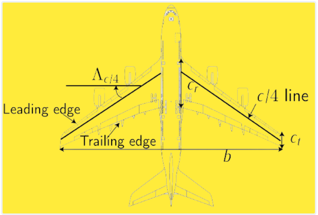
Geometry and Nomenclature of a Commercial Aircraft Wing:
To fully understand the geometry and nomenclature of a typical commercial aircraft wing, it’s essential to familiarize oneself with the following key elements:
- Wingspan (b):
- The wingspan refers to the distance between the wingtips, extending from one end of the wing to the other. It represents the total width of the wing.
- Chords:
- Root Chord (cr): The chord length at the wing root, typically where the wing attaches to the fuselage.
- Tip Chord (ct): The chord length at the wingtip, representing the width of the wing at its outermost point.
- Leading and Trailing Edges:
- Leading Edge: The forward-facing edge of the wing, usually rounded to minimize drag and improve aerodynamic efficiency.
- Trailing Edge: The rear edge of the wing, where airflow separates from the wing surface as it moves aft.
- c/4 Line:
- The line corresponding to the locus of c/4 points is a reference line located a quarter of the chord length back from the leading edge along the chord line. It helps determine critical aerodynamic properties and balance points.
- Swept Angle at c/4 (Λc/4):
- The angle formed by the chord line and the c/4 line is known as the swept angle at c/4. It represents the angle at which the wing is swept back from the leading edge, affecting aerodynamic characteristics and stability.
- Wet Wing Surface (Sw):
- The area enclosed by the leading and trailing edges, along with the marginal borders (the section with cr view in a plant-form), is defined as the wet wing surface. It represents the total surface area of the wing exposed to airflow.
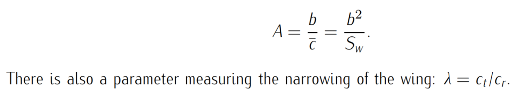
- Geometric Mean Chord (¯c):
- The geometric mean chord is the average chord length of the wing and is calculated by dividing the wet wing surface (Sw) by the wingspan (b). It provides a representative measure of the wing’s overall chord length, akin to a rectangular wing with the same area and wingspan.
The enlargement, A, is defined as:
Flow Over a Finite Wing:
When analyzing the aerodynamics of aircraft, particularly those with finite wings like commercial airplanes, it’s crucial to understand how airflow interacts with the wing structure.
Flow over a finite wing involves complex interactions between the wing geometry, airflow, and aerodynamic forces. Here’s a detailed explanation:
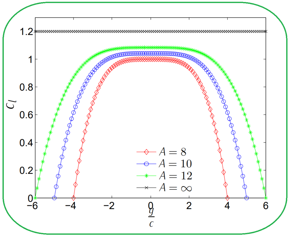
Coefficient of Lift Distribution:
- Figure below depicts the distribution of coefficient of lift (Cl) along the wingspan of four rectangular wings at an attack angle of 10 degrees. These wings have the same aerodynamic airfoil but differ in their enlargements (8, 10, 12, and infinity).
- When the enlargement is infinite, the wing behaves like a two-dimensional airfoil, with Cl being constant along the span. However, for finite enlargements, Cl exhibits a maximum at the wing root (y = 0) and decreases to zero at the wingtip (y/c = A/2).
- As the enlargement decreases, the maximum Cl also decreases, indicating the influence of wing geometry on lift distribution.
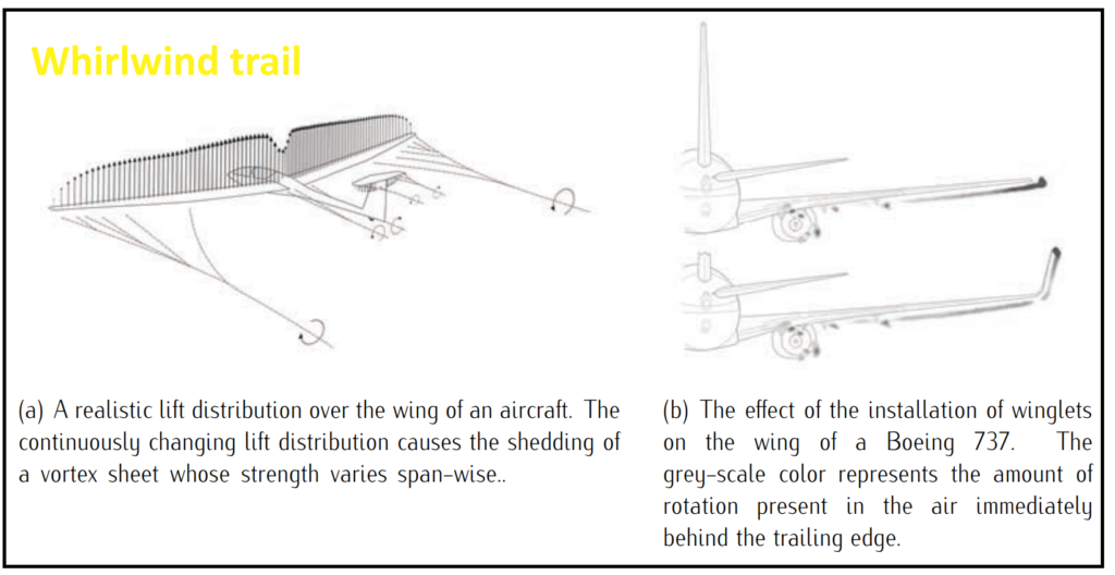
Pressure Difference and Vortices:
- The variation in Cl along the wingspan is due to the pressure difference between the extrados and intrados of the wing.
- Near the marginal border, an air current surrounds the wing, moving from the intrados (higher pressure) to the extrados (lower pressure), generating two vortices, one clockwise and one counterclockwise.
- These vortices create a whirlwind trail downstream of the wing, modifying the fluid field and affecting the airflow over the wing.
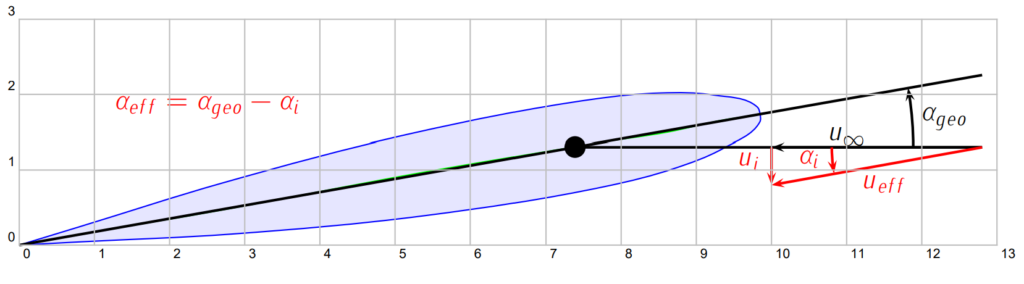
Induced Velocity:
- The presence of the vortex trail alters the velocity profile seen by each section of the wing’s airfoil.
- In addition to the freestream velocity (u∞), a vertical induced velocity (ui) is induced by the vortices.
- The induced velocity increases closer to the marginal border, resulting in a lower effective angle of attack for the airfoil compared to the geometric angle.
- This reduction in effective angle of attack explains the decrease in Cl with proximity to the marginal border and the overall modification of lift distribution along the wingspan.
Understanding the flow over a finite wing and its effects on lift distribution is crucial for optimizing wing design and improving aircraft performance. By considering the complex interplay between wing geometry, pressure distribution, and vortex dynamics, engineers can develop more efficient and stable aircraft configurations.
Lift and induced drag in wings
Lift and induced drag are two important aerodynamic forces experienced by wings during flight.
Lift:
- Lift is the aerodynamic force that opposes gravity and keeps an aircraft aloft. It is generated primarily by the wings through the process of airflow over the wing’s surface.
- The generation of lift is attributed to the difference in air pressure between the upper and lower surfaces of the wing. The curved shape of the wing, known as the airfoil, accelerates airflow over the top surface, creating lower pressure, while the airflow under the wing experiences higher pressure.
- This pressure difference results in an upward force perpendicular to the relative airflow, which is the lift force. The magnitude of lift depends on various factors, including wing shape, angle of attack, airspeed, and air density.
- Lift is essential for maintaining flight and controlling the altitude and maneuverability of an aircraft.
Induced Drag:
- Induced drag is a byproduct of lift generation and is caused by the production of lift-induced vortices at the wingtips.
- As air flows over the wing, it creates low-pressure areas above the wing and high-pressure areas below it. This pressure difference induces airflow around the wingtips, resulting in the formation of swirling vortices.
- These vortices, also known as wingtip vortices or trailing vortices, create an additional downwash behind the wing, altering the airflow downstream.
- The downwash reduces the effective angle of attack of the wing, leading to an increase in the angle of attack required to maintain lift. This increase in angle of attack results in an increase in induced drag.
- Induced drag is proportional to the lift coefficient squared and inversely proportional to the aspect ratio of the wing. Therefore, wings with higher aspect ratios (longer and narrower) experience lower induced drag.
- Induced drag is a significant component of total drag, particularly at lower airspeeds and during high-lift conditions, such as during takeoff and landing.
The lift coefficient CL is a dimensionless quantity used to represent the lift produced by an airfoil or wing. It is defined as the ratio of
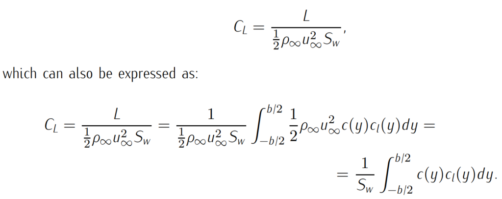
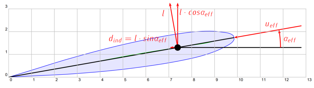
The induced velocity created by the wing’s downwash leads to the appearance of induced drag. This drag component arises because the lift force is not purely perpendicular to the freestream direction, resulting in a component of lift acting parallel to the airflow. This induced drag is an important consideration in aerodynamics, influencing the overall drag experienced by the aircraft and affecting its performance characteristics.
Characteristic curves in wings
Characteristic curves in wings, also known as aerodynamic performance curves, are graphical representations of various aerodynamic properties of a wing or airfoil. These curves provide valuable insights into the behavior and performance of the wing under different operating conditions.
The lift curve and the drag polar are important tools for understanding the aerodynamic behavior of an aircraft. Let’s delve into each of these curves and their significance:
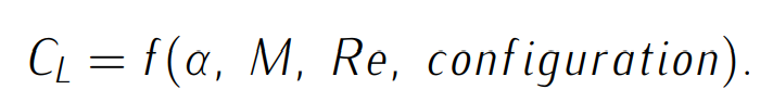
Lift Curve:
The lift coefficient CL characterizes the lift generated by the wing and is influenced by various factors such as angle of attack α,, Mach number (M), Reynolds number (Re), and the configuration of the aircraft (e.g., flaps). A general expression for the lift coefficient is given as:
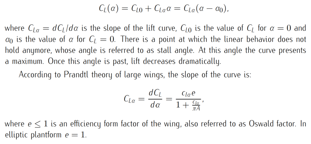
In many cases, the lift curve exhibits a linear zone that can be approximated by:
Drag Polar:
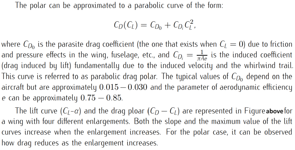
The drag polar relates the coefficient of drag CD to the coefficient of lift CL and provides insights into the aircraft’s drag characteristics. The drag coefficient depends on CL, Mach number, Reynolds number, and aircraft configuration. It can be expressed as:

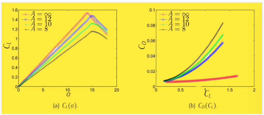
In summary, the lift curve and drag polar provide valuable insights into the aerodynamic performance of an aircraft, helping engineers optimize wing design and predict aircraft behavior under different flight conditions.
Aerodynamics of wings in compressible and supersonic regimes
In compressible and supersonic regimes, the aerodynamics of wings exhibit similarities to those of airfoils but with additional considerations due to the three-dimensional nature of wings and the effects of sweep angle.
1. Swept Wings:
Swept wings are commonly used in aircraft design to reduce the effective Mach number experienced by the wing. This reduction factor is approximately cosine of the quarter-chord sweep angle (∆c/4). By reducing the effective Mach number, the wing behaves as if it were flying at a slower speed, allowing for higher divergence Mach numbers.
2. Supercritical Airfoils:
While swept wings help delay the onset of divergence, they also lead to decreased values of CLα (lift coefficient slope) and CLmax (maximum lift coefficient). To mitigate these effects, especially in commercial aviation where high lift and efficiency are crucial, supercritical airfoils are often employed. Supercritical airfoils feature a flattened upper surface and a more gradual pressure recovery, allowing for higher critical Mach numbers and improved performance at high speeds.
3. Supersonic Flight:
In supersonic flight, wings are typically designed with significant sweep and small aspect ratios. The extreme example of this design approach is the delta wing configuration. Delta wings offer advantages such as high lift-to-drag ratios, structural simplicity, and efficient performance at supersonic speeds. They are commonly used in supersonic and hypersonic aircraft, as well as in certain military and experimental aircraft.
4. Structural Complexity:
While swept and delta wings offer aerodynamic advantages in compressible and supersonic regimes, they also introduce structural complexity and engineering challenges. The integration of swept wings with aircraft structures, control surfaces, and systems requires careful design and analysis to ensure safety, stability, and performance.
In summary, the aerodynamics of wings in compressible and supersonic regimes involve trade-offs between sweep angle, airfoil design, and structural considerations. Swept wings and supercritical airfoils are employed to optimize performance at high speeds, while delta wings offer unique advantages for supersonic flight. Each design choice reflects a balance between aerodynamic efficiency, structural integrity, and operational requirements in high-speed flight environments.