Instrument Technician Using PPE (Personal Protective Equipment)
Safety Document
Maintenance Work Permits. & SCC (Safety Clearance Certificate) If Required
Tools/ Special
I & C Tool Kit + any special tools (if Required)
Test Equipment
Tools
Test Equipment:
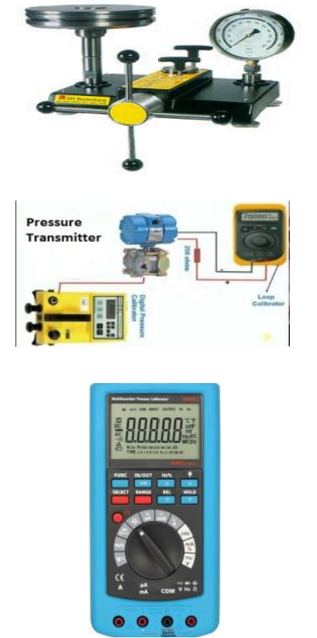
Note: Select test equipment according to the max. Range & Medium.1– AVO meter / mA meter
2– Deadweight Tester, Standard Pressure Gauge (0.5 Bar to 200 Bars)
3– Hydraulic pressure pump and standard pressure gauge (0 Bar to 250 Bars). 4– Air pressure pump with digital multifunction calibrator used for very low and low pressure (0 to 20000mmH2O or 0to 2 Bar or 0 to 20 Bars). 5– Water manometer or mercury manometer with air pump (0 to 1500 mm H2O or 0 to 1500mmHg). 6- Vacuum pump with digital multifunction tester.(0 to -760 mmHg / 0 to -30 inches of Hg or 0 to -1 Bar)
Stores &Materials
Cleaning spray, brush and cloth
Job Description
Process
Steps
During Maintenance
Isolation& Removal
1
Isolate the transmitter by closing inlet valves of many fold or isolate from the main isolating valves of impulse lines.
2
In case of oil or chemical process use secondary container to avoid spill of oil / chemical when isolating. Depressurize the pressure transmitter and draining tapping lines.
3
Confirm that power supply is OFF. Remove the wires from the transmitter terminal by the core identification and insulate all wires terminals by insulation tape (Ensure it isn’t in contact with each other, short circuiting or producing any earth).
4
Move away the tapping lines to avoid spill of oil or chemical from transmitter connections. Disconnect the pressure transmitter or differential pressure transmitter from the process carefully.
5
Carry out the Pressure transmitter / diff. pressure transmitter external cleaning, using a brush and approved cleaning spray to remove contamination or solid particles.
6
Inspect the Pressure or Diff. Pressure Transmitter for external physical damage, general appearance & fitness. (Check whether cover seals are intact).
Preparation
7
Write all the details of pressure or diff. pressure transmitter, tag no., range, service and unit no. in the calibration sheet.
8
Collect the calibration range from MEW Engineer of each transmitter (millimeter WC till maximum range in bars) and note in the calibration sheet.
9
Damping of Transmitter: Damping means a delay between change in the transmitter inputs and detection of change to the output values. Mostly it is a mechanical screw type damping adjustment on the diff. pressure transmitter. It is better to adjust the transmitter damping value at zero before performing calibration. Note the position of damping pointer. After test re-adjust the original value of damping before installing in field.
10
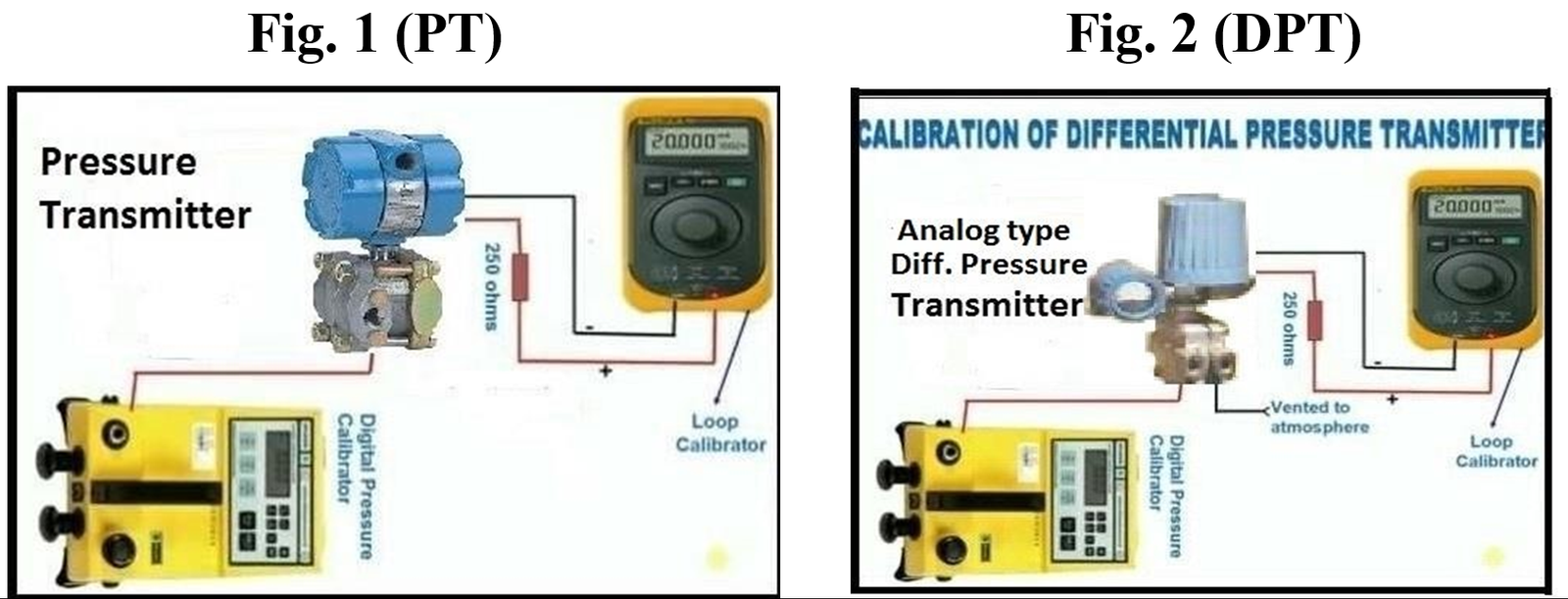
Set up the test equipment as shown in the diagram:
11
Ensure that the medium used for calibration is same as that of medium of the process (if possible).
12
Carry out purging (if required) to remove the process medium completely from the transmitter internals (pressurize, fill and then drain).
13
Carry out the leak test by applying the pressure to the transmitter & check for leakages. (Pressurize at max. range and wait for at least one minute). If there is any leakage in connections, tighten. Note:1– Always use high pressure port of Diff. pressure transmitter and keep low pressure port free in air for reference. 2- Never apply pressure more than the rated pressure; otherwise pressure sensor of transmitter will be damaged.
14
Connect the power supply 24VDC to the transmitter and mA meter to read output 4~20mADC during calibration.
Note: Multi-function calibrator can be used for both functions. As a power source and to read out 4~20mADC.
15
Exercise the pressure element to stretch for full range and back to zero to make sure that element can operate normal.
Calibration
16
Without applying pressure, check the output of transmitter should be 4mADC.
17
Now apply 100% pressure according to range provided by MEW Engineer and note the output of transmitter. It should be 20mADC. Note: This pressure can be applied in increasing and decreasing order i.e. Ascending or descending order (e.g Increasing like: 0%, 25%, 50%, 75% & 100%) and vice versa.
18
If output of the above both values are correct then check middle 3 points (at 25% input pressure, output = 8mADC, at 50% input Pressure, output =12mADC and at 75% input pressure, output=16mADC) for rising and falling values.
19
In case of Vacuum transmitter. Without creating vacuum check the output current should be 4.00mADC. Now create the vacuum in the vacuum transmitter and note the other 4 points input / output values. (At 25% vacuum: output should be 8.00mADC, at 50% vacuum: output current should be 12mADC, at 75% vacuum: output should be 16mADC & at 100% vacuum: output should be 20mADC). Note: If we consider 0% vacuum at 20mADC then at 100% vacuum, current should be 4.0Madc
20
Record these input/output values in the calibration sheet in as found column or before calibration column.
21
If all reading are correct and error is in limit & below the design values then go to step 29.
22
If there is difference in reading more than error then adjustment is required. Remove covers (if available) to gain access to zero adjustment and span adjustment screw.
23
De-pressurize the transmitter completely to check 4.00mADC at the 0% input pressure, adjust transmitter output 4mADC by zero adjustment screw
24
Apply 100% input pressure to the transmitter and view the output of transmitter it should be at 20mADC. If it is less or more, then adjust the span screw to keep the current at 20mADC.
24
Repeat steps 23 and 24 till at 0% input pressure, output should be 4.00mADC & 100% input pressure, output should be 20mADC.
26
If zero and span became correct then check the other 3 points i.e. at 25% input pressure = 8mADC, at 50% input pressure = 12mADC and at 75% input pressure = 16mADC by increasing and decreasing the pressure.
27
Check repeatability by increasing and decreasing pressure and confirm all 5 points (0%, 25%, 50%, 75%, & 100%) input / output values match with standard values. Check the error is in limit and under design value.
28
Record these input & output values in calibration sheet in after calibration columns.
29
The pressure transmitter or diff. pressure transmitter input / output values should be inspected by MEW Inspector and Quality Inspector for witness and record these values to sign the certificate after completion of job.
30
It is necessary to adjust head correction (If any) to avoid any wrong reading.
Completion
31
Once the test is completed, remove the test equipment and clean the tested device.
32
Install the pressure or diff. pressure transmitter back to its position and reconnect the instrument fittings, tubing without bending or damaging and ensure that connector is not cross fitted that can damage threading.
33
After test, re-adjust the original value of damping before installing in field.
34
Close the drain valve and open the inlet valve slowly to avoid sudden pressure entering in the transmitter sensor.
35
In case of water / oil / chemicals, purge the air completely from the transmitters, tub lines / capillary tube and fill the transmitter carefully to avoid showing any wrong readings.
36
Check for leakage during commissioning.
37
Complete the check and calibration sheet and handover to the concerned MEW I&C Engineer for inspection and signature.