Instrument Technician Using PPE (Personal Protective Equipment)
Safety
Maintenance Work permit & SCC (Safety Clearance Certificate) If Required.
Document
Tools/ Special
I &C Tool Kit + any special tools (if Required)
Test Equipment
Tools
Test
Note: Select test equipment according to the max.
Equipment:
Range & Medium.1– AVO meter / Contact Tester
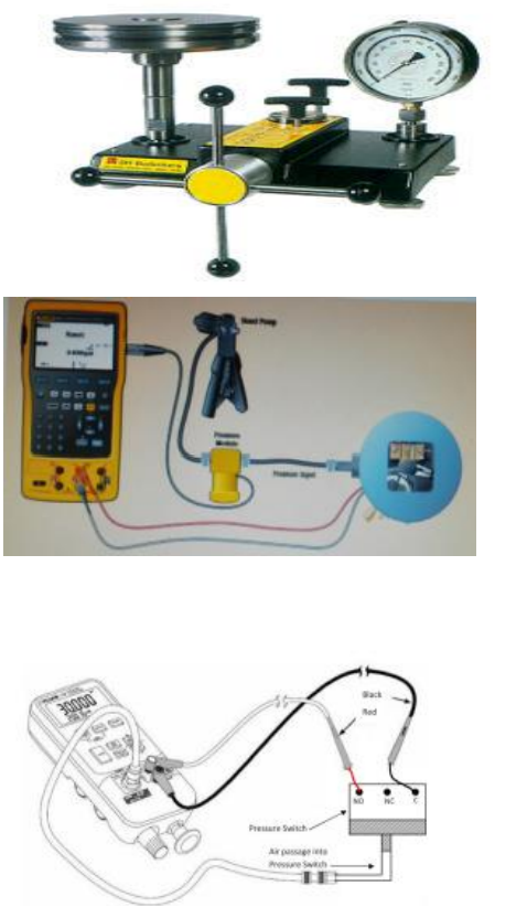
2– Deadweight Tester, Standard Pressure Gauge (0.5 Bar to 200 Bars)
3– Hydraulic pressure pump and standard pressure gauge (0 Bar to 250 Bars). 4– Air pressure pump with digital multifunction calibrator used for very low and low pressure (0 to 20000mmH2O or 0to 2 Bar or 0 to 20 Bars). 5– Water manometer or mercury manometer with air pump (0 to 1500 mm H2O or 0 to 1500mmHg). 6- Vacuum pump with digital multifunction tester.(0 to -760 mmHg / 0 to -30 inches of Hg or 0 to -1 Bar)
Stores & Materials
Cleaning spray, brush and cloth
Job Description
Process
Steps
During Maintenance
Isolation& Removal
1
Isolate the pressure switch by closing inlet valve of many fold or isolate from the main isolating valve of impulse line.
2
In case of oil or chemical process use secondary container to avoid spill of oil / chemical when isolating. Depressurize the transmitter and draining tapping lines.
3
Ensure by multi meter that power supply is OFF. Remove the wires from the switch terminal by the core identification and insulate all wires by insulation tape (Ensure it isn’t in contact with each other, short circuiting or producing any earth)
4
Remove the capillary tube or dampener carefully to clean and repair. Move away the tapping lines to avoid spill of oil or chemical from switch connections. Disconnect the pressure switch form the process carefully
5
Carry out the Pressure switch external cleaning, using a brush and approved cleaning spray to remove contamination or solid particles.
6
Inspect the Pressure switch for external physical damage, general appearance & fitness. (Check whether cover seals are intact).
Preparation
7
Write all the details of pressure switch: tag no., range, service and unit no. in the calibration sheet.
8
Damper should be removed before calibration and note the setting before servicing.
9
Set up the test equipment as shown in the below diagram:
10
Ensure that the medium used for calibration is same as that of medium of the process (if possible) where pressure switch is installed.
11
Carry out purging (if required) to remove the process medium completely from the pressure switch internal (pressurize, fill & then drain).
12
Carry out the leak test by applying the pressure to the pressure switch & check for leakages. (Pressurize at full scale and wait for at least one minute). If there is any leakage in connections, tighten. Note:1– Always use high pressure port of Diff. pressure switch and keep low pressure port free in air for reference. 2- Never apply pressure more than the rated pressure; otherwise pressure sensor of switch will be damaged. 3- In case of PGA (Pressure Gauge Alarm), Use Procedure SCP-PG-01 to calibrate pressure gauge. After calibrating pressure gauge go to next step for calibrating switch.
13
Exercise the pressure switch sensing element to stretch for full scale and back to zero to make sure pressure element is operating normally.
14
Tap the pressure gauge with switch (PGA) gently to ensure there is no friction and the pressure sensor moves freely and not loosely fixed.
15
If you feel any friction, then remove the front cover to gain access to see the physical condition of internal parts. Check the pressure sensor for any physical damage.
16
Check the moving parts from sensor to the micro switch for possible deformation. Apply small amount of silicon grease to the moving parts (Repairs or replace internal parts if damaged).
17
Note down the SP values (1SPDT OR 2SPDT) on the calibration sheet supplied by MEW for set and reset (increasing SP for high pressure switch & decreasing SP for low pressure switch) and contacts (NO or NC) used in
the pressure switch.
18
If head correcting is necessary then add this head value in the set point value and then calibrate switch to avoid the wrong alarm and trip.
19
Check the contacts of micro switch by ohm meter. Zero resistance should be in micro switch contacts. If resistance is high clean the contacts by dry contact cleaning spray (If possible), If then also resistance is high change the micro switch with new one.
Calibration
20
Apply input pressure to the pressure switch. (Either increasing or decreasing corresponding to the use of pressure switch for high SP or low SP pressure).
21
Increase the pressure and check the set value when micro switch changes its position from NO to NC or NC to NO on the contact tester
22
Decrease the pressure and check the reset value on the contact tester (Micro switch will change from NC to NO or NO to NC)
23
Repeat step 21 &22 to confirm the set and reset values of the pressure switch are matching with MEW supplied set point.
24
Write the input pressure set & resets values (SP) in the Calibration Sheet in the column as before calibration
25
In case of 2nd SPDT repeat step 21&22 to confirm the set and reset values of the 2nd switch are matching with 2nd values SP supplied by MEW.
26
If set and reset values are correct of both SPDT and matching with MEW supplied SP then go to step 35.
27
If a set and reset value differs from the MEW supplied SP then it is required to change the set and rest values as stated in next step.
28
Remove any additional cover necessary to gain access to the set point adjustment and differential adjustments. Inspect the Pressure Switch for internal physical damage, general appearance and fitness. Check that the cover seals are in good condition. Record findings on the check and calibration sheet.
29
Increase the pressure and check the set value when micro switch changes its position from NO to NC or NC to NO on the tester, and adjust the set value screw till it reaches to the set point.
30
Decrease the pressure and check the reset value on the tester (Micro switch will change from NC to NO or NO to NC). Adjust the Differential adjustment screw to get exact value of reset.
31
Repeat steps 29 & 30 (1SPDT & 2SPDT) by increasing and decreasing pressure. Adjust the SP screw and differential adjustment screw as set and rest values (SP) until it reaches at correct values and match with MEW supplied SP. Note: (In case of Vacuum switch) Create the vacuum to adjust SP.
32
If the Pressure switch adjustments are over, check & confirm by the repeatability of the switch for the designed setting of SP.
34
If the calibration adjustment is successful, Record the after adjustment results (Re-adjusted SP values) on the check and calibration sheet in after adjustment column.
35
The pressure switch set and reset values (SP) should be inspected by MEW Inspector and Quality Inspector for witness and record these values to sign the certificate after completion of job.
Completion
36
Once the test is completed, remove the test equipment and clean the tested device.
37
Install the Pressure switch back to its position and reconnect wires on its terminals ensure good fixings. Refit the covers ensuring that all their seals are fitted and that all screws are tight. Reconnect the instrument fittings, tubing without bending or damaging and ensure that connector is not cross fitted that can damage threading.
38
If there is damper or capillary tube used before the pressure switch. It should be checked and cleaned or overhauled. (Replace gaskets or O-rings if necessary in damper). Reset the position of damper on its set position as found before service.
39
Close the drain valve and open the inlet valve slowly to avoid sudden pressure entering in the switch sensor.
40
In case of water / oil / chemicals, purge the air completely from the pressure switch, tub lines / capillary tube and fill carefully.
41
Check for leakage during commissioning and tighten.
42
Complete the check and calibration sheet and handover to the concerned MEW I&C Engineer for inspection and signature.