This article is about Pressure & Differential Pressure Gauges Calibration Procedure. Following instruments to be calibrated by our given procedure.
1- Pressure Gauge & Pressure gauge with alarm (PGA)
2- Differential Pressure Gauge & DPGA Indicating type
3- Compound Gauge
4- Vacuum Gauge
General Procedure for all Power Stations
Maintenance Check & Calibration
Instrument Technician Using PPE (Personal Protective Equipment)
Maintenance Work Permits. & SCC (Safety Clearance Certificate) If Required
Tools / Special
Tools
I &C Tool Kit + any special tools (if Required) Test Equipment
Test Equipment:
Note: Select test equipment according to the max.
Range & Medium.
1- Deadweight Tester, and Standard Pressure Gauge (0.5 Bar to 200 Bars)
2- Hydraulic pressure pump and standard pressure gauge (0 Bar to 250 Bars).
3- Air pressure pump with digital multifunction calibrator used for very low and low pressure (0 to 20000mmH2O or 0to 2 Bar or 0 to 20 Bars).
4- Water manometer or mercury manometer with air pump (0 to 1500 mm H2O or 0 to 1500mmHg).
5- Vacuum pump with digital multifunction tester.(0 to – 760 mmHg / 0 to -30 inches of Hg or 0 to -1 Bar)
Isolation & Removal
- Isolate the gauge by closing inlet valve of many fold or isolate from the main isolating valve of impulse line.
- In case of oil or chemical process use secondary container to avoid spill of oil / chemical when isolating. Depressurize the gauge; drain tapping lines to remove the gauge.
- Remove the capillary tube or dampener carefully to clean and repair. Move away the gauge tapping lines to avoid spill of oil or chemical from gauge connections. Disconnect the pressure gauge form the process carefully.
- Carry out the Pressure Gauge external cleaning, using a brush and apply cleaning spray to remove contamination or solid particles.
- Inspect the Pressure Gauge for external physical damage, general appearance & fitness. (Check whether cover seals are intact).
Preparation
- Write all the details of pressure gauge: tag no., range, service and unit no. in the calibration sheet.
- Damper should be removed before calibration and note the setting before servicing.
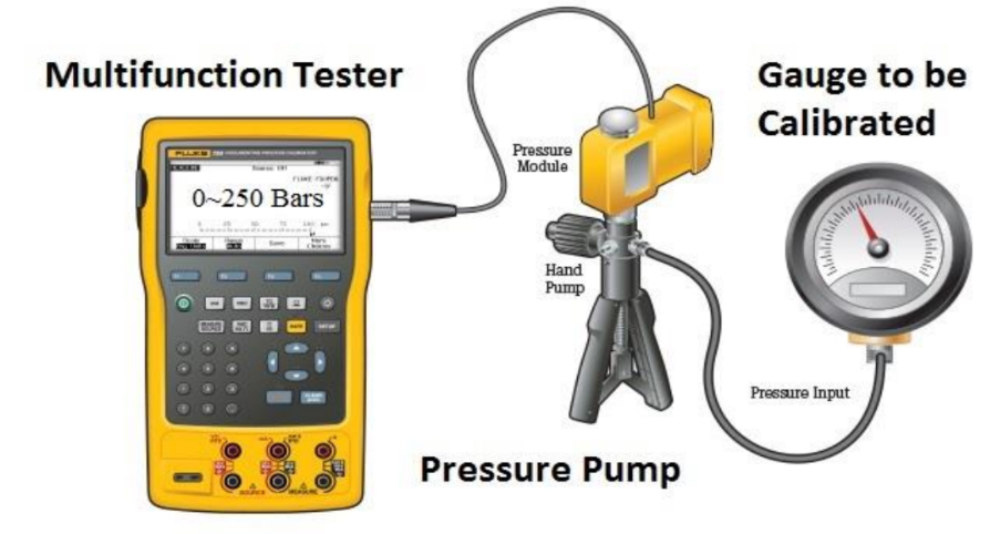
- Set up the test equipment as shown in the diagram:

- Ensure that the medium used for calibration is same as that of medium of the process (if possible) where pressure gauge is installed.
- Carry out purging (if required) to remove the process medium completely from the pressure gauge internal sensor (pressurize, fill & then drain).
- Carry out the leak test by applying the pressure to the pressure gauge & check for leakages. (Pressurize at full scale and wait for at least one minute). If there is any leakage in connections, tighten. Note:
- 1- Always use high pressure port of Diff. pressure gauge and keep low pressure port free in the air for reference.
- 2- Never apply pressure more than the rated pressure; otherwise pressure sensor of gauge will be damaged.
- Exercise the gauge element to stretch for full scale and back to zero to make sure gauge element is operating normally.
- Tap the gauge gently to ensure there is no friction and the needle moves freely and not loosely fixed to the gauge element. Go to step 02 in Calibration Section.
- If you feel any friction remove the front cover, pointer and scale plate to gain access to see the physical condition of internal parts.
- Check the hair spring, gears of pinion and rack, bushings, (There should be no large gap in between bushing and spindle) and the bourdon tube for possible deformation. Apply small amount of silicon grease to the moving parts. (Repairs or replace internal parts if damaged).
Calibration
- Now install the scale & pointer after making internal inspections. Check and adjust pointer at (0) position on the scale.
- Without applying pressure check “0” of the gauge. Now apply pressure to required percentage (25%, 50%, 75% or 100%) for rising and falling values (ascending and descending values). Record these values in the calibration sheet before calibration column.
- Note: (1) We are checking ascending and descending to find the hysteresis in between increased reading and decreased reading.
- (2) In case of vacuum gauge: without creating vacuum check the “0” of the gauge, then create the vacuum in the vacuum gauge or compound gauge and note the other 4 points value (25%, 50%, 75% & 100%) Record these values in the calibration sheet.
- If all reading are correct and error is in limit & below the design values then record these values in after calibration column and go to step 10.
- If there is difference in reading is more than error and adjustment is required then remove the front cover, pointer and scale plate to gain access to span adjustment.
- Increase pressure or create vacuum up to maximum scale and observe the difference in between standard values on the tester and pressure gauge to be calibrated. In case of any difference more than the error, adjust the span screw to increase or decrease span as required.
- Depressurize the gauge completely to check the (0) value and adjust the pointer on zero if required.
- Repeat steps 05 and 06 till 0% & 100%. Values should match with standard values.
- Now check the percentage (0%, 25%, 50%, 75%, & 100%) by increasing and decreasing the pressure. Check the error is in limit and under design value.
- Record these input & output values in the calibration sheet after calibration columns.
- The pressure gauge input / output values should be inspected by MEW Inspector and Quality Inspector for witness and record these values to sign the certificate after completion of job.
- It is necessary to adjust head correction to avoid any wrong reading. (If required)
Completion
- Once the test is completed, remove the test equipment and clean the tested device.
- Install the Pressure gauge back to its position and reconnect the instrument fittings, tubing without bending or damaging and ensure that connector is not cross fitted to avoid damage to threading.
- If there is damper or capillary tube used before the pressure gauge, it should be checked and cleaned or overhauled. (Replace gaskets or O-rings if necessary in damper). Reset the position of damper on its set position as found before service.
- Close the drain valve and open the inlet valve slowly to avoid sudden pressure entering in the gauge sensor.
- In case of water / oil / chemicals, purge the air completely from the pressure gauge, tub lines / capillary tube and fill the gauge carefully to avoid showing wrong readings.
- Check for leakage during commissioning.
- Complete the check and calibration sheet and handover to the concerned MEW I&C Engineer for inspection and signature.