1- Analog Temperature Indicator. (ATI) (Input Thermocouple any type ) (Input RTD any type )
| Procedure | General Procedure for all stations. | ||
| Title of Job | Maintenance Check & Calibration | ||
| Manpower | Instrument Technician Using PPE (Personal Protective Equipment) | ||
| Safety Document | Maintenance Work Permits. & SCC (Safety Clearance Certificate) If Required | ||
| Tools/ Special | I &C Tool Kit | Test Equipment | |
| Tools | |||
| Test Equipment: | |||
| Note: Select test equipment according to the max. Range of Analog Temperature Indicator. 1- Digital precession multifunction Temperature Calibrator. 2-Multifuction HART Calibrator |  | ||
| Stores & Materials | Cleaning spray, brush and cloth | ||
Analog temperature indicator Calibration Procedure
| Job Description | ||
| Process | Steps | During Maintenance |
| Isolation & Removal | 1 | Open the back cover of Analog Temperature Indicator (ATI) to gain access to the wires. Remove the power supply wires and T/C or RTD input wires by the core identification and insulate all wires by insulation tape (Ensure it isn’t in contact with each other, short circuiting or producing any earth). Note: (1) This type of ATI can be calibrating at their locations. (2) Mostly all Mfg. Companies manufacture analog indicators with Zero and Span adjustment screws as shown in above diagram. (Yamatake Co. provides Zero and Span adjustment screws installed in distillation plants) (3) Some Mfg. companies only provide Zero adjustment screw. Span screws are not provided. In these indicators we can adjust only zero. (YEW & Bailey Co. only provided Zero adjustment screw installed in Boiler 1~4 and Turbine 1~4) 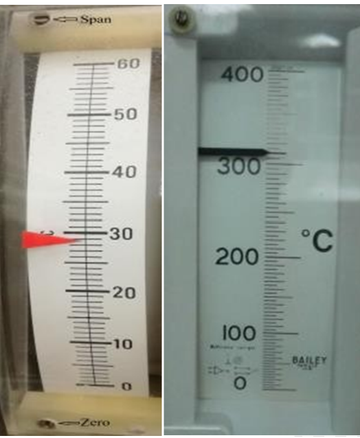 |
| 2 | Carry out the ATI external cleaning, using a brush and approved cleaning spray to remove dust, contamination or solid particles. | |
| 3 | Inspect the ATI for external physical damage, general appearance & fitness. | |
| Preparation | 7 | Write the all detail of Analog Temperature Indicator Tag No., Service, and Unit No. in the Calibration & Test sheet |
| 8 | View the Temperature range in C of the ATI and input device (T/C or RTD) data and record in the calibration sheet. | |
| 9 | Set up the test equipment as shown in the diagram of Thermocouple input.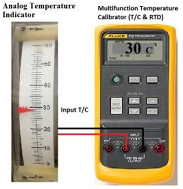 | |
| 10 | Set up the test equipment as shown in the diagram of: RTD input.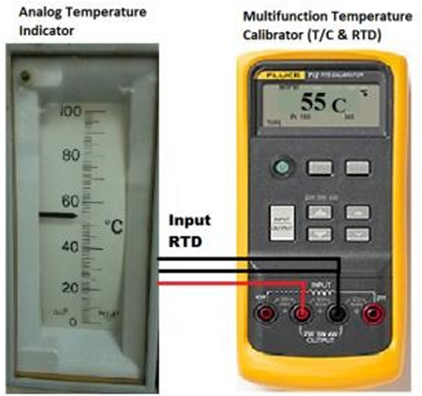 | |
| 11 | Connect the power supply wires to the ATI Power terminals and Switch ON the power supply. | |
| 12 | Switch ON Digital Precession Multifunction Temperature Calibrator and select the type of input. If it is T/C then select Thermocouple on the multifunction temperature calibrator. Now select the type of thermocouple. “T” type, or “J” type or “K” type or any other type used with this ATI. | |
| 13 | If input is RTD, then select RTD on the Digital Precession Multifunction Temperature Calibrator. Now select he type Pt100Ω with 3 wires. Or any other type. Note: Digital precession multifunction Temperature Calibrator has built in temperature compensator (Separate temperature compensator is not required). | |
| Calibration | 14 | Now apply 5 points (0%, 25%, 50%, 75% and 100%) temperature from the calibrator and see the reading on the Analog temperature indicator. It should show temperature according to the input temperature. |
| 15 | Record these temperature readings in as found column or before calibration column. If error is within limit and acceptable then go to step 25. | |
| 16 | If error is more than the designed error then ATI needs to be calibrated. |
| 17 | Now apply “0” degree C or 0% temperature from the multifunction temperature calibrator, if it is not 0 C then adjust zero from zero adjustment screw on the ATI. | |
| 18 | Now apply 100% temperature from the multifunction temperature calibrator, if it is not 100% then adjust span from span adjustment screw. | |
| 19 | Repeat step 17 & 18 till the 0% and 100% reading of ATI should match with input temperature. | |
| 20 | Now apply again 5 points (0%, 25%, 50%, 75% and 100%) temperature from the temperature calibrator and see the reading on the Analog temperature indicator. It should match according to the input temperature and error should be in limit. | |
| 21 | If the calibration adjustment is successful, record the after adjustment results on the check and calibration sheet in after adjustment column. | |
| 22 | If there is only Zero adjustment screw available in the indicator (Like YEW & Bailey Co. only provided Zero adjustment screw installed in Boiler 1~4 and Turbine 1~4) then divide error on all reading that error should become in limit. If still error is more, then replace the indicator with new indicator. | |
| 23 | The Analog temperature indicator calibration should be inspected by Inspector and Quality Inspector for witness and record these values to sign the certificate after completion of job. | |
| Completion | 24 | Once the test is completed, remove the test equipment and clean the tested device. |
| 25 | Install the Analog Temperature Indicator back to its position (If it is removed) and connect all wires at original positions according to the core identification. | |
| 26 | Switch ON the power supply and Commission the Analog Temperature indicator. Check the reading on ATI. It should be nearly ambient temperature because unit is shut-down or under annual maintenance. | |
| 27 | Complete the check and calibration sheet and handover to the concerned I&C Engineer for inspection and signature. |