1- PID Controller (Compact Unit)
2- PID Controller (Module Based)
| Procedure | General Procedure for all Power Stations. | ||
| Title of Job | Maintenance Check & Calibration | ||
| Manpower | Instrument Technician Using PPE (Personal Protective Equipment) | ||
| Safety Document | Maintenance Work Permits. & SCC (Safety Clearance Certificate) If Required | ||
| Tools/ Special | I &C Tool Kit + any special tools (if Required) | Test Equipment | |
| Tools | |||
| Test Equipment: | Note: Select test equipment according to the Test loop. 1- Loop Tester / Simulator. 2- Digital multimeter. 3- Multifunction Calibrator. 4- Stopwatch. |  | |
| Stores & Materials | Cleaning spray, brush and cloth | ||
PID Controller Function Test Procedure
| Job Description | ||
| Process | Steps | During Maintenance |
| Isolation & Removal | 1 | Plant should be shut down or under maintenance. |
| 2 | Process line should be isolated from the both side of the control valve. | |
| Preparation | 3 | Work permit should be available with maintenance engineer. |
| 4 | Air supply of control valve should be normalized. | |
| 5 | Control valve should be in working condition. | |
| 6 | Check I/P converter calibration has been done. | |
| 7 | Check the valve position indicator calibration has been done. | |
| 8 | Check the control valve calibration has been done. | |
| 9 | Above all calibration confirmation is required to minimize the control loop error. | |
| 10 | Identify the control loop to be tested. For Example: (LRC-102 / A1) Last stage Brine level or (LRC-103/A1) Last stage distillate. | |
| 11 | Remove the input wires of process variable coming from the field Level transmitter to the cubical terminals for Level Indicator & PID controller. Insulate the removed wires with insulation tape with core identification. (For example: Unit: A1, Analog cubical No. Terminal No. CT5, terminals 3&4 for last stage brine) or | |
| (Unit: A1, Analog cubical and terminal No.CT5, terminals 5&6 for last stage distillate level). | ||
| 12 | Fix a loop tester in series with mA meter on the removed wires terminals with core identification. (For example: Unit A1, CT5, terminals 3(+) & 4(-) or 5(+) & 6(-) | |
| 13 | Check the PV by changing current 4~ 20mADC = 0%, 25%, 50%, 75% & 100% on the recorder and set point indicator. | |
| 14 | Check the PV Input “1~5VDC” on the PID controller test points, should be equal to 4~20mADC / 0~100% input current. | |
| 15 | Set up the PID Compact control test loop as shown in fig. 1 Fig.1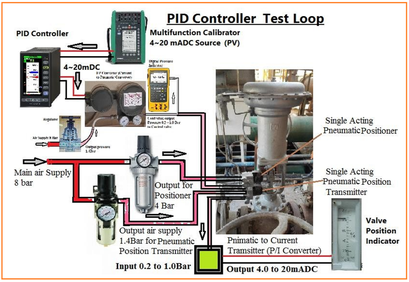 | |
| 16 | Set up the module based PID control test loop as shown in fig. 2 Fig. 2 | |
| Test | 17 | Write the all details of PV, PID controller and control valve, Tag No., Service and Unit No. in the calibration & Test sheet. |
| Procedure | 18 | Note the all P.I.D. set values in test sheet before test. | |
| 19 | Make the all P.I.D. Values Zero before test. (PB. Reset & derivative) | ||
| 20 | Actions of Control Valves: Before we start the test we should understand & keep in mind that we have 2 actions of control valves. Option 1: Control valve is installed on the discharge line of the Pump and it is controlling the tank level before the pump. Means CV is installed on outgoing water from the tank. As shown in fig. 3. Result: So in this situation if tanks level will increase valve will open to decrease the level and if tank level decrease the valve will close to increase the level. In Option 1, during test we have to reduce the SP from 50%. Option 2: Control valve is installed before the tank but controlling the tank level at the inlet of the tank. Means CV is installed incoming water to the tank. As shown in fig. 3. Result: So in this situation if tank level will increase, valve will close to decrease the level and if level decrease, valve will open to increase the level. In Option 2, during test we have to increase the SP from 50%. Means valve action will be inversely proportion to the PV. Fig.: 3  | ||
| We have 7 stages to test a PID controller. Keep in mind Knob type of PID controller have visible error to set exact position. | |||
| 21 | 1- PID Controller Balance Test. Note: PB is inversely proportional to Gain output. Increase of PB means Gain output will be decrease. (PB=100%, Gain output will be 0%). Fig. 4  | ||
| 22 | Before test start we can check the set point output voltage is matching with percentage (If possible). 0%=1V, 25%=2V, 50%=3V, 75%=4V & 100%=5VDC. |
| 23 | Inject process variable (PV) at 50%=12mADC=3 VDC from loop tester / Simulator (This PV will be input of controller) | |
| 24 | Now set the PB=100%, Integral time / Rest time=0, Derivative time=0 | |
| 25 | Set the SP at 50%=3VDC (We have already set process variable at 50% =12mADC =3 VDC) & Valve position=50% | |
| 26 | Change A/M station on Auto and watch the control valve movement. Note: Valve should not move in above conditions. This means control loop is balanced. | |
| 27 | 2- Off Set Test: By Changing A/M station on Auto if valve moves means there is OFF Set in between SP & PV. Means PID controller module is not 100% accurate as shown in fig.: 5 Fig. 5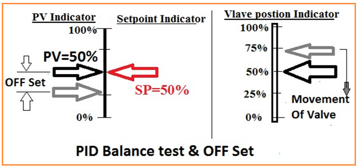 | |
| 28 | If valve moves to open means PB is not accurate 100%. Reduce little PB (-) or increase PB (+) and again check balance test. | |
| 29 | Repeat step 26, 27 & 28 until valve should not move. Note this new setting of PB. This new setting of PB will be 100% accurate. Mark on the dial 100% PB and readjust knob pointer on this new seting. | |
| 30 | Note: (a) If any adjust is required then PID controller module card should be calibrated according to the manufacturer calibration procedure. (b) In PID compact controller there will be no error. (These are expected to be very accurate). | |
| 3– Proportional Action Test: | ||
| 31 | Set the PB=30%, Reset time =100%, Derivative time=0%, PV & Set point =50% & Valve position=0% | |
| 32 | Change A/M station on Auto. Now change the set point from 50% to 25% and watch the movement of control valve. Valve should move up to 75 ~ 80%. If it not reaches, then calculate the difference between SP-PV and adjust PB by controller knob. (If possible) | |
| 4- Integral or Reset Action: | ||
| 33 | Set PB=100%, Reset time=100%, Rate time: 0, PV & SP=50% & valve position=0%. | |
| 34 | Change A/M station on Auto. Now reduce the set point from 50% to 25%. Watch the movement of valve. Valve should open 25%. |
| 5- Reset Time Test: | ||
| 35 | Set PB=100%, Reset time: 2 Minute, Rate: 0, SP & PV=50% & valve position=0%. | |
| 36 | Change A/M station on Auto. Now change the set point from 50% to 25%. Watch the movement of valve. 1st valve will open suddenly25% then valve will open from 25% to 50% by the action of PB, and then from 50% to 75% valve will open by the action of reset time. | |
| 6– Derivative time: (It is also called “Rate” or Pre-Act) | ||
| 37 | Set PB=100%, Reset time=100% & Rate=1Min. | |
| 38 | SP & PV=50% & Valve should be fully closed. Keep the stop watch ready to start. Note: Valve should smooth open. Not to be stuck with rubber. | |
| 39 | Change A/M station on Auto and reduce the SP 15% down form the 50%. Watch the valve movement. | |
| 41 | The valve will start to open and will reach to max. Position (70 ~ 80%) Now valve will come back to close very fast. | |
| 42 | Now start “stop watch”, when valve come back from (70~80%) & till valve reaches to 40 to 45%. At 40~45% valve closing speed will be reduced. Note the time duration. | |
| 43 | The time from 70~80 % to 40~45% should be 2 ~ 20 Seconds. This time is called derivative action time. | |
| 7– Controller Action of control valve with PID settings. | ||
| 44 | Set PB=60%, Reset time=2 Min. & Rate=1Min. & SP & PV=50% & valve position = 0%. | |
| 45 | Change A/M station on Auto. | |
| 46 | (a) Now increase the PV mA, Valve should open to decrease the PV. | |
| 47 | (b) Now decrease the PV mA, Valve should close to increase the PV. | |
| 48 | If test values are correct and error is in acceptable limit. Record these test values in calibration & test sheet. | |
| 49 | The PID Controller with control valve should be inspected by MEW Inspector and Quality Inspector for witness and record these test steps to sign the certificate after completion of job. | |
| Completion | 50 | Once the test is completed, remove the test equipment. |
| 51 | Reconnect the PV input wires with core identification to the terminals. | |
| 52 | Set the P.I.D. controller set values as we noted before test. | |
| 53 | Normalize control valve by opening inlet outlet isolating valve. |