1- Single Acting Control Valve with a SMART Positioner. (Direct Action and Reverse Action Actuator)
| Procedure | General Procedure for all Power stations and refineries. | ||
| Title of Job | Maintenance Check & Calibration | ||
| Manpower | Instrument Technician Using PPE (Personal Protective Equipment) | ||
| Safety Document | Maintenance Work Permits. & SCC (Safety Clearance Certificate) If Required | ||
| Tools/ Special | I &C Tool Kit + any special tools (if Required) | Test Equipment | |
| Tools | |||
| Test Equipment: | Note: Select test equipment according to the Test loop. 1- 4~20mADC source. 2- Multimeter (AVO). 3- Multifunction precision Calibrator | 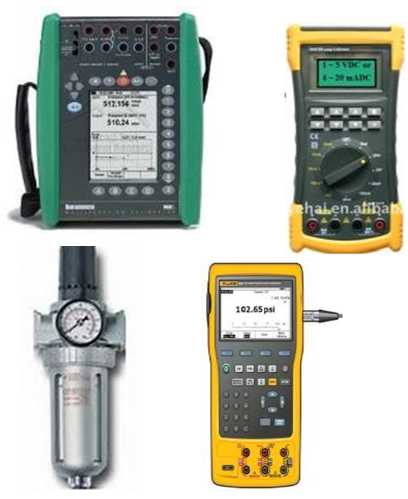 | |
| 4- HART communicator. | |||
| 5- Air Filter Regulator (0~2bar) | |||
| 6- Standard Pressure gauge (0~2Bar) | |||
| Stores & Materials | Cleaning spray, brush and cloth | ||
| Job Description | |||
| Process | Steps | During Maintenance | |
| Isolation | 1 | We have 2 types of Single acting (Diaphragm | |
| & | operated) control valve with a SMART Positioner | ||
| Removal | 1- Direct Action Control Valve 2- Reverse Action Control Valve | ||
| Note:(1) SMART positioner is one touch calibration. (2)SMART Positioner works as 4 in 1 (It eliminates I/P converter, Pn. Positioner, Pn. position transmitter & P/I converter) | 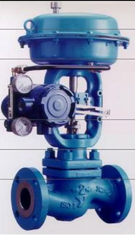 Fig. 1 Fig. 1 | ||
| 2 | Valve should be on manual position from the auto manual station form the control room (Unit should be shut-down or annual maintenance). | ||
| 3 | Control valve should be isolate by isolating inlet and out let valve of the process line by operation department. | ||
| 4 | Carry out the control valve and accessories external cleaning, using a brush and approved cleaning spray to remove contamination or solid particles. | |
| 5 | Carry out the SMART positioner external cleaning, using a brush and approved cleaning spray to remove contamination or solid particles. | |
| 6 | Inspect control valve actuator and accessories external physical damage, general appearance & fitness (Check whether cover seals of accessories are intact). | |
| 7 | Inspect SMART positioner external physical damage; general appearance & fitness (Check whether cover seals are intact). | |
| 8 | Open the cover of SMART positioner and disconnect input and output wires carefully with core identification and insulate the all wires with insulation tape. | |
| Preparation | 9 | Write all the details of control valve: tag no., service, and unit no. in the calibration sheet. |
| 10 | Air leak test of actuator should be perform to confirm there should be no air leak from anywhere of the actuator. (Leak test should be done according to the Air Leak Test Procedure Ref.: SCP-AALT-24). | |
| 11 | Stroke adjustment shall be checked. Re-adjust the stroke if required. (When actuator is fully close then mechanical valve should be also fully closed and there should be no passing in this situation.) | |
| 12 | Open the back cover of SMART positioner to clean the nozzle flapper as shown in fig. 2 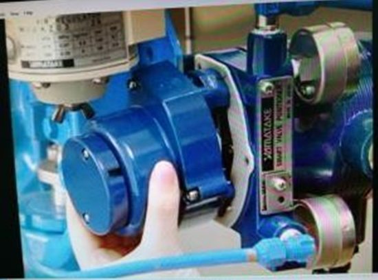 Fig.2 Fig.2 | |
| 13 | Clean the nozzle flapper by taking a paper with thickness of 0.5mm and move in between nozzle and flapper as shown in fig. 3 After cleaning fix back the cover. 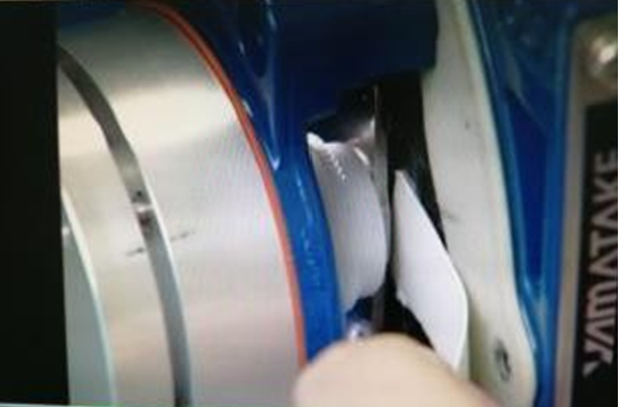 Fig. 3 | |
| 14 | Set up the test equipment with multifunction calibrator as shown in fig. 4  Fig. 4 | |
| 15 | Another Set up the test equipment can be used with HART Communicator as per the diagram shown in the fig. 5.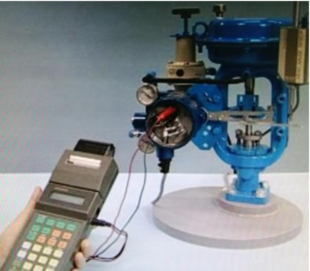 Note: We can also configure and calibrate SMART Positioner by this communicator. |
| Calibration | 16 | Insert 4mADC from the mA source or multifunction calibrator. The valve should not move from 0% Position. Check on the Mechanical indicating plate should show 0% Position. |
| 17 | SMART positioner will transmit 4~20mADC signal to control room for position indicator (This will work like position transmitter) Check the position on the multifunction calibrator should be 0.0%, means it is 4.00 mA on mA meter output of positioner. Note: Mean time it can show us stroke in mm on the multifunction calibrator if this option is available in multifunction calibrator. | |
| 18 | Now insert 8mA, 12mA, 16mA & 20mA accordingly from the mA source or multifunction calibrator. Let the valve should travel to 25%, 50%, 75% & 100% Position accordingly. Check current output from the SMART positioner to control room. It should be 8.0mA, 12.00mA, 16.00mA and 20.00mA accordingly. Note: View on the mechanical indicating plate should also be showing all above values accordingly. | |
| 19 | Check the repeatability in ascending and descending order from 0 to 100% and from 100% to 0% accordingly. | |
| 20 | If calibration values are correct and error is acceptable limit. Record these input & output values in calibration sheet in as calibration columns or before calibration column and go to step 33. | |
| 21 | If input values not matching with output position values means calibration is required. Note: SMART positioner calibration is very easy. It is called one touch calibration. (Automatic calibration will be done by SMART positioner) | |
| 22 | Set 18mADC on the multifunction calibrator as shown in step 14 in fig.4. | |
| 23 | Take a screw driver (-) and turn the screw full right turn (Upward as shown on the plate.). Hold for 3 seconds as shown in this fig.6. When valve move to closed position leave the screw. Screw will come back its original position. 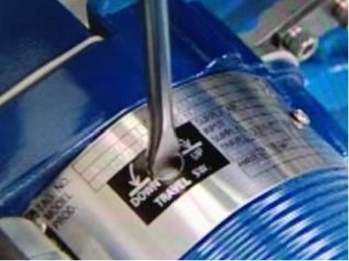 Fig. 6 Note: (1) Automatic calibration will start. (2) Now only view the automatic calibration. No need to touch. |
| 24 | In 1st step valve will move to 0% Position. Now SMART positioner will start to adjust C/V at 0%. Also output for position transmitter will be adjusted at 0% Position. Wait till it stabilizes the all values at 0% position. | ||||
| 25 | In 2nd step valve will move to 100%. SMART positioner will adjust the valve 100% position of C/V. Wait till it stabilizes the all values of 100% Position. | ||||
| 26 | In 3rd step valve will move again to 0% position to confirm the 0% position. | ||||
| 27 | In 4th step valve will move to 50% Position. This means calibration is over. | ||||
| 28 | Now confirm the 5 point calibration. Insert the 0%, 25%, 50%, 75% and 100% input current and view the valve position on the indicating plate and also view the position on the multi-function calibrator or output 4~20 mADC on multimeter. | ||||
| 29 | We can also confirm 5 points calibration | ||||
Manual position of Auto / Manual screw form Auto to Manual position as shown in fig. 7.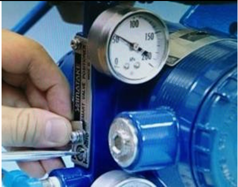 | |||||
| 30 | Now operate the air filter regulator manually for 0%=0.2bar, 25%=0.4bar, 50%=0.6 bar, 75%=0.8 bar and 100%=1.0 bar. as shown in fig.8.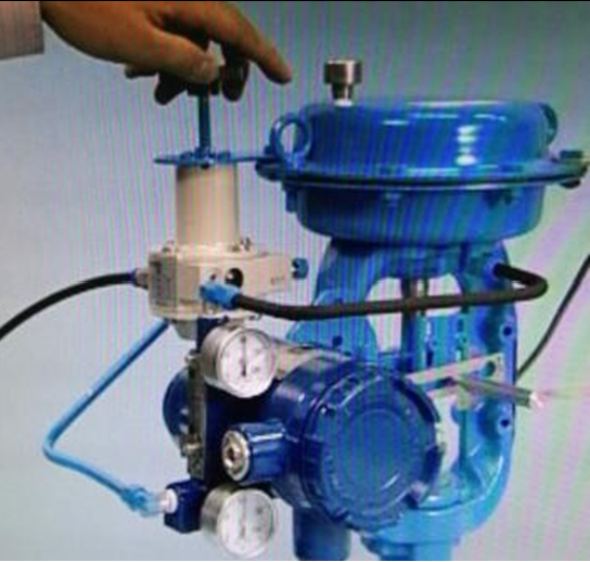 Note: indicating plate also view output current 4~20 mADC on multimeter. | ||||
| 31 | In case of over traveling movent of C/V more than 100%. Adjsut the strok by terning UP and Down Screw of SMART Poitioner as shown in fig. 6. Note: Up and down screw should move up and down but not hold on up and down position. | ||||
| 32 | If calibration values are correct and error is acceptable limit. Record these input & output values in calibration sheet in after calibration columns. | ||||
| 33 | The control valve calibration input / output values should be inspected by Inspector and Quality Inspector for witness and record these values to sign the certificate after completion of job. | ||||
| Completion | 34 | Once the test is completed, remove the test equipment and clean the tested device | |||
| 35 | Reconnect the input / output wires with core identification to SMART positioner. | |
| 36 | Reconnect the instrument fittings, tubing without bending or damaging and ensure that connector is not cross fitted that can damage threading. (If removed) | |
| 37 | Open the main air supply valve to the regulators and adjust output pressure accordingly. | |
| 38 | Check for leakage of air during commissioning and retighten the instrument fittings. | |
| 39 | Complete the check and calibration sheet and handover to the concerned I&C Engineer for inspection and signature. |