What is Automatic Transfer Switch?
An Automatic Transfer Switch (ATS) is a critical component of an electrical power system that is designed to automatically and seamlessly transfer the electrical load from one power source to another in the event of a power outage or when there is a change in the primary power source’s availability or quality. ATSs are commonly used in backup power systems, such as standby generators or uninterruptible power supplies (UPS), to ensure uninterrupted electrical power to essential equipment or circuits.
Automatic Transfer Switch Basics:
Transfer switches are fundamental components in critical power systems, ensuring that electrical loads can seamlessly transition between normal and emergency power sources. Here’s a breakdown of some key concepts related to transfer switches:
1. Normal and Emergency Power Sources: Facilities like data centers, hospitals, and factories rely on a continuous power supply. The normal power source is the primary electrical supply, typically provided by the utility grid. The emergency power source, often a backup generator or a secondary utility feed, comes into play when the normal power source fails.
2. Transfer Switch Function: Automatic Automatic Transfer switches are responsible for managing the transition of electrical loads between these power sources. They ensure that power is efficiently and safely rerouted to maintain uninterrupted operation.
3. Load: The load refers to all electrical devices, circuits, equipment, or systems connected to the output of the transfer switch. This can include critical equipment, lighting, HVAC systems, and more.
4. Transfer Sequence: The typical transfer sequence involves the following steps:
- Normal Power Failure: When the normal power source fails or becomes unstable (e.g., due to a blackout), the transfer switch detects this condition.
- Switch to Emergency Power: If the emergency power source (e.g., generator) is stable and within specified voltage and frequency tolerances, the transfer switch shifts the electrical load to the emergency source. This transfer can occur automatically or manually, depending on the type of switch and its configuration.
- Return to Normal Power: When utility power is restored and is stable within specified tolerances, the Automatic transfer switch transfers the load back from the emergency source to the normal source. Again, this transition can be automatic or manual.
5. Automatic and Manual Operation: Transfer switches can operate in automatic mode, where they detect power source changes and execute transfers without human intervention. In manual mode, an operator initiates the transfer based on their judgment or specific procedures.
6. Importance of Voltage and Frequency Tolerances: Transfer switches rely on prescribed voltage and frequency tolerances to ensure the quality and compatibility of the power source. Deviations outside these tolerances may trigger or prevent transfers.
7. Facility-Specific Configuration: The type of transfer switch and its operation mode (automatic or manual) can vary based on the specific needs and preferences of a facility. Some applications require immediate, automatic transfers to maintain uninterrupted operation, while others may allow for manual intervention.
Automatic Transfer switches play a crucial role in maintaining uptime and ensuring that critical systems continue to receive power during unexpected outages or emergencies. They are a critical component of overall electrical infrastructure in facilities where uninterrupted power is essential.
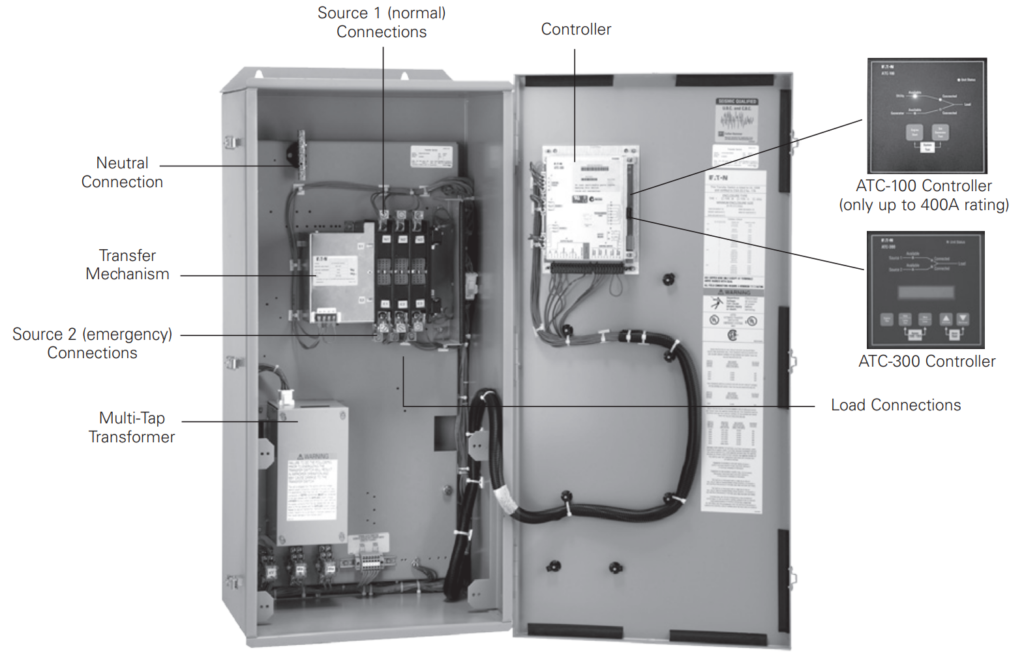
Components of Automatic Transfer Switch (ATS):
Following are the list of ATS components:
- Controller.
- ATC-100 or 300 Controller.
- Source 1 Normal Connections.
- Load Connections.
- Multi-Tap Transfer.
- Source 2 Connections (For Emergency)
- Transfer Mechanism.
- Neutral Connection.
Common System Installation Types of ATS:
Transfer switches are used in various applications classified into four categories as defined by the National Electrical Code® (NFPA 70). These categories help determine the type of automatic transfer switch required for a specific application:
1. Emergency Systems:
- Purpose: Emergency systems are designed to supply, automatically distribute, and control electricity for systems crucial to life safety during emergencies, such as fires and disasters.
- Typical Loads: These systems power essential equipment like fire detectors, alarms, emergency lights, elevators, fire pumps, public safety communication systems, and ventilation systems.
- Locations: Commonly found in hotels, theaters, sports arenas, hospitals, and other facilities.
- Regulatory Oversight: Emergency systems are regulated by governmental agencies at municipal, state, federal, or other levels.
- Transfer Time: Transfer from normal power to the emergency source must occur within 10 seconds, meeting the requirements of Article 700 of NFPA 70.
2. Legally Required Systems:
- Purpose: Legally required systems automatically provide power to specific regulated loads that are not categorized as emergency systems when normal power is unavailable.
- Typical Loads: These systems support critical functions like heating, refrigeration, communication, ventilation, smoke removal, sewage disposal, and lighting.
- Locations: Found in places where a loss of electrical power could pose hazards or hinder rescue or firefighting efforts.
- Regulatory Oversight: Similar to emergency systems, legally required systems are subject to regulations enforced by governmental agencies.
- Transfer Time: Transfer from normal power to the emergency source must occur within 60 seconds, complying with Article 701 of NFPA 70.
3. Critical Operations Power Systems (COPS):
- Purpose: COPS supply, distribute, and control electricity in designated critical areas when normal power sources fail.
- Typical Loads: These systems serve functions like HVAC, fire alarms, security, communication, signaling, and other services in facilities deemed important for national security, the economy, or public health and safety.
- Regulatory Oversight: COPS must meet the requirements of Article 708 of NFPA 70, and their overcurrent devices must be selectively coordinated with supply-side overcurrent protective devices.
4. Optional Standby Systems:
- Purpose: Optional standby systems provide power to loads that are not directly related to life or health safety and are not required to function automatically during power outages.
- Typical Loads: These systems supply power to loads with no immediate impact on safety, often found in commercial buildings, farms, residences, and similar settings.
- Regulatory Oversight: These systems are subject to the requirements of Article 702 of NFPA 70.
Understanding these categories is essential in determining the specific regulatory requirements and the type of automatic transfer switch needed for each application. It ensures that the proper equipment is in place to maintain power continuity for critical systems and functions during normal and emergency situations.
Transition Types of ATS:
Transfer switches facilitate the transition of electrical loads between normal and emergency power sources, and this transition can occur in two basic ways: open transition and closed transition. The choice of transition type depends on the specific functions of the loads and their importance to safety and security.
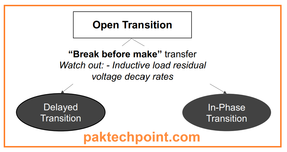
Open Transition:
In an open transition, also known as a “break before make” transfer, the automatic transfer switch disconnects from one power source before connecting to the other. During a brief period between disconnection and connection, neither the normal power source nor the emergency source supplies electricity to the downstream loads. There are two subtypes of open transition: open delayed and open in-phase.
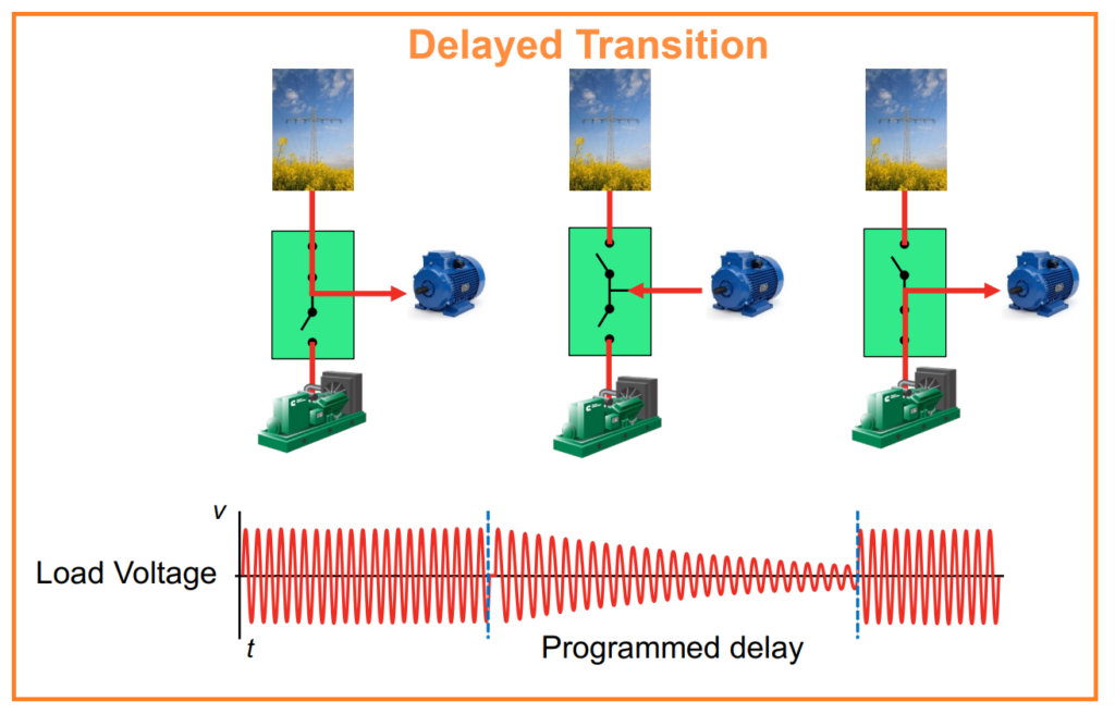
Open Delayed Transition:
- Delayed Pause: During the transition, there is a pause or delay in which the automatic transfer switch remains disconnected from both power sources.
- Delay Types: The delay can be a preset time interval or last until the load voltage drops below a specified level.
Advantages: - Prevents inrush current, which can occur when rapidly reconnecting inductive loads to a non-synchronized power source.
- Independent of electrical synchronization between power sources.
- Can be initiated automatically or manually.
Disadvantages:
- Unless there is a downstream stored energy system (e.g., uninterruptible power supply), loads experience a brief power interruption during the transition delay.
Open In-Phase Transition:
- Rapid Transition: In open in-phase transitions, an automatic controller initiates the transition at the precise moment when it expects the normal and emergency power sources to be synchronized in phase, voltage, and frequency.
- Speed: These transitions typically take 150 milliseconds or less to ensure that inrush current is minimal.
- Failsafe: If synchronization doesn’t occur within the specified time frame, some automatic transfer switches can default to a delayed transition as a failsafe measure.
Advantages: - Rapid transition minimizes power interruption to the load when the system is properly adjusted.

Disadvantages:
- Requires an automatic controller for execution; manual operation is not possible.
- If both power sources are available but unable to meet preset synchronization criteria, and the transfer switch cannot default to a delayed transition, a transfer will not occur.
The choice between open and closed transition depends on factors like the load’s sensitivity to power interruptions and the system’s capacity to manage inrush current. Each type has its advantages and limitations, making them suitable for different applications.
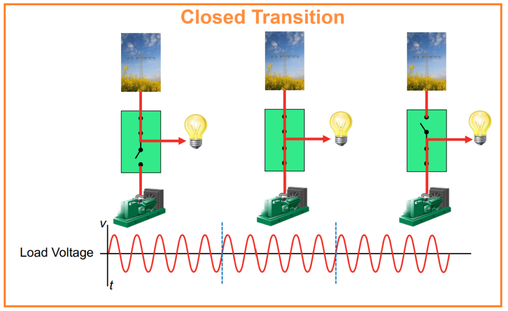
Closed Transition:
A closed transition, also known as a “make before break” transfer, operates differently from open transition. In a closed transition, the automatic transfer switch establishes a connection to the new power source before disconnecting from the old one. This means that there is no gap between disconnection and connection, ensuring that downstream loads receive uninterrupted power throughout the transition.
Closed transitions typically occur automatically as soon as both power sources are closely synchronized in phase, voltage, and frequency. During this process, both sources are simultaneously connected, or “paralleled,” for a brief period, usually lasting no more than 100 milliseconds, to comply with local utility interconnect requirements.
Advantages:
- Critical loads can continue to operate without any interruption in power, even during loaded generator engine testing.
- Energy costs can be reduced through “peak shaving,” which allows control of usage from a utility during high-demand intervals to limit or reduce demand penalties during billing periods.
- Depending on the application, closed transitions may eliminate the need for an uninterruptible power supply (UPS) downstream.
Disadvantages:
- Transfer switches configured for closed transitions tend to be more expensive.
- Some utilities require closed transitions to comply with interconnect requirements aimed at preserving power quality and protecting utility service personnel and equipment. This may necessitate the inclusion of protective relays in the electrical circuit.
- Closed transitions must be executed by an automatic controller; manual operation is not possible, as microprocessor logic is required to manage source synchronization.
- Closed transitions can result in higher fault current due to the 100-millisecond period when both power sources are paralleled. As a result, consulting engineers may specify a higher withstand close-on rating (WCR), potentially requiring oversizing of the automatic transfer switch amperage rating.
Closed transitions offer advantages such as continuous operation of critical loads and potential cost savings but may require more sophisticated equipment and careful consideration of utility requirements and equipment ratings.
Automatic Transfer Switch Switching Mechanisms:
There are three types of witching Mechanisms of ATS.
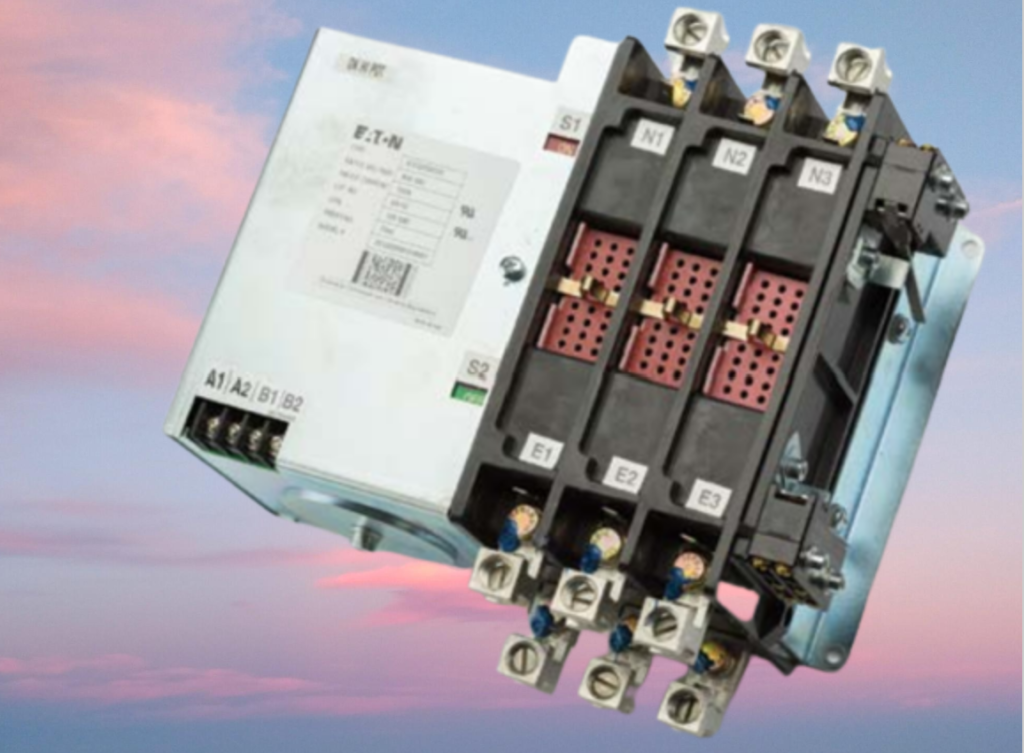
1. Contactor Switching Mechanisms:
Contactor switching mechanisms are one of the two basic types of low-voltage switching mechanisms used in transfer switches. These mechanisms are commonly used due to their affordability and versatility. They function as double-throw switches, where a single operator can open one set of power contacts while simultaneously closing another set. It’s important to note that in an open transition design, a mechanical interlock is often included to prevent both contact sets from closing simultaneously, whereas this interlock is absent in a closed transition design.
Advantages:
- Contactor switching mechanisms support all three transition types: open delayed, open in-phase, and closed transitions.
- Transfer switches equipped with contactor switching mechanisms are generally more cost-effective.
Disadvantages:
- Contactor switching mechanisms do not include integral overcurrent protection, which means the power contacts are not self-protecting. In the event of a fault, these contacts will typically remain closed, and the system’s safety relies on other protective devices in the electrical circuit to address the issue.
- The withstand close-on rating (WCR) for contactor switching mechanisms may be lower compared to circuit breaker switching mechanisms at rated amperage.
Contactor switching mechanisms are versatile and budget-friendly but may require additional protective devices for fault handling and have limitations in terms of withstand close-on ratings.
2. Molded Case Switching Mechanisms:
Molded case switching mechanisms are another type of low-voltage switching mechanism used in transfer switches. These mechanisms are designed to close and interrupt circuits between separable contacts, operating under both normal and abnormal conditions. Molded case switches feature a straightforward design and can support either manual operation via an over-center toggle or motorized operation. They are typically housed in insulating material enclosures.
In automatic transfer switch applications, a pair of molded case switches is operated through a common mechanical linkage, which can be controlled either manually or automatically. When overcurrent protection is required, molded case circuit breakers equipped with a thermal-magnetic trip element are used.
Advantages:
- Contacts in molded case switching mechanisms are self-protecting at high fault currents due to integral magnetic sensing.
- These mechanisms can be configured with integral overcurrent protection, providing “lock-out” functionality and preventing automatic transfers into a fault condition.
- Molded case switching mechanisms can be manually operated under load, thanks to their “quick make/quick break” over-center toggle switching action.
- They provide high withstand close-on ratings (WCR) at lower amperages, eliminating the need for oversized automatic transfer switch frame sizes to meet specifications.
Disadvantages:
- Molded case switching mechanisms are generally more expensive than contactor switching mechanisms.
- They do not support closed or in-phase transitions.
Molded case switching mechanisms offer the advantage of self-protecting contacts and high WCR at lower amperages, making them suitable for applications where integral overcurrent protection is required. However, they are typically more costly and do not support certain transition types.

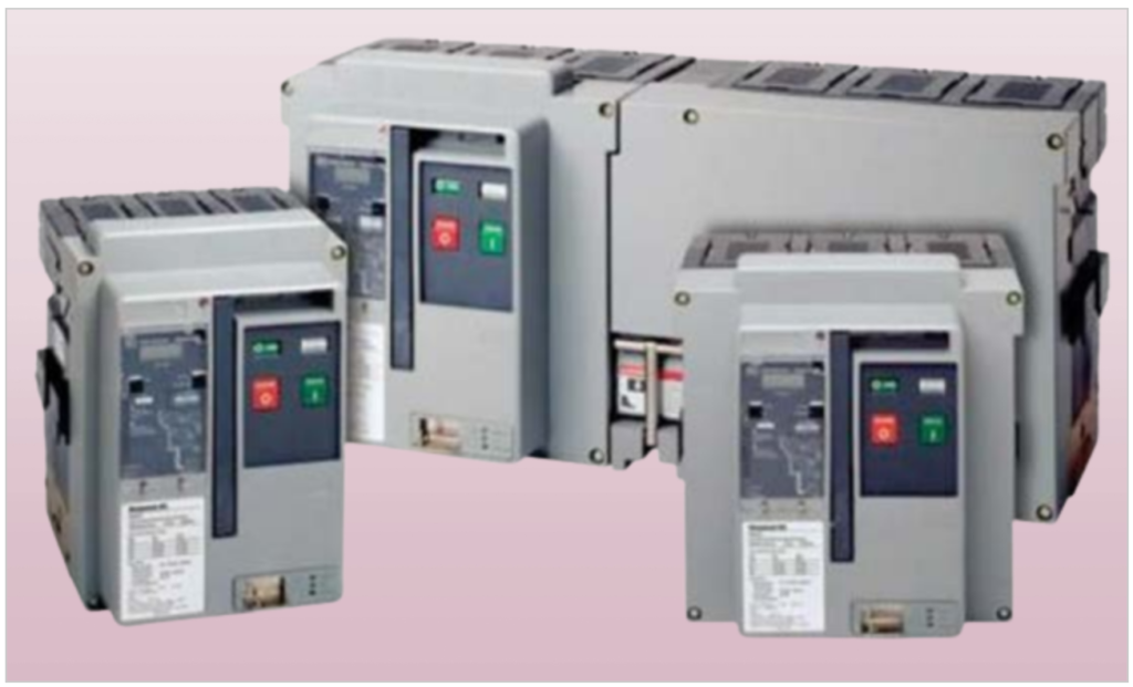
3. Power Case Switching Mechanisms:
Power case switching mechanisms are a robust and high-capacity type of low-voltage switching mechanism used in automatic transfer switches. These mechanisms are larger, faster, and more powerful compared to molded case mechanisms, capable of handling amperages up to 5,000 amps. They utilize two-step stored energy technology, enabling both mechanical and electrical operation. Some models of power case mechanisms also feature integral overcurrent protection, similar to molded case designs.
Advantages:
- Power case switching mechanisms can be configured with various trip unit types, offering integral and programmable overcurrent protection, ground fault sensing, power quality metering, and diagnostics.
- They provide the highest withstand and amperage ratings among all switching mechanism designs.
- Rapid closing speeds make them suitable for in-phase, closed, and delayed transitions.
- Power case mechanisms can be configured for “selective coordination,” allowing the protective device upstream of an electrical fault to open first, ensuring the rest of the power distribution system remains operational. This is especially important for applications like emergency, COPS (Critical Operations Power Systems), and legally required systems.
Disadvantages:
- Power case switching mechanisms are larger in size compared to contactor and molded case designs.
- They are typically the most expensive among the three switching mechanism types.
Power case switching mechanisms offer a high level of flexibility and protection, making them suitable for applications requiring precise coordination and protection against large fault currents. However, their larger size and cost should be considered when selecting them for specific applications.
Understanding Operation Modes of Automatic Transfer Switches:
Transfer switches can operate in various modes to manage the initiation and completion of power transfers between different sources. These operation modes provide flexibility and options for different applications. Here are the key operation modes:
1. Manual Mode:
- Initiation: Manual transfers require human intervention, typically by pressing a button or moving a handle.
- Operation: The operator manually controls the transfer process.
- Advantages:
- Transfers can occur under load in case of controller or circuitry issues.
- Maximum control over the process.
- Independent of the automatic controller.
- Disadvantages:
- Requires a physical operator at all times.
- Transition delay depends on the operator.
- Limited to open delayed transitions.
- Safety concerns as operators may need to access energized equipment.
- Prohibited in some emergency and legally required installations.
2. Non-Automatic Mode:
- Initiation: Manually triggered by an operator using a button or switch.
- Operation: An internal electromechanical device operates the switching mechanism.
- Advantages:
- Operators initiate transfers.
- Faster transitions compared to manual mode.
- Lower cost compared to automatic switches.
- Disadvantages:
- Requires a human operator.
- No support for open in-phase or closed transitions.
3. Automatic Mode:
- Initiation: Automatic controller senses power unavailability and initiates the transfer.
- Operation: Electric solenoid or motor performs the switching.
- Advantages:
- Fast and automated transitions.
- No need for a human operator.
- Greater flexibility with programmable settings.
- Compliance with NEC requirements for emergency and legally required systems.
- Disadvantages:
- Higher cost compared to manual or non-automatic switches.
4. Bypass Isolation Mode:
- Initiation: Automatic controller or manual operator can initiate.
- Operation: Dual switching mechanisms provide redundancy for critical applications.
- Advantages:
- Safe service and maintenance without interrupting power to critical loads.
- Built-in redundancy with a secondary mechanism.
- Disadvantages:
- Higher cost due to dual switching mechanisms.
- Larger size compared to traditional automatic transfer switches.
Each operation mode has its own set of advantages and disadvantages, making them suitable for different applications based on factors like cost, criticality of loads, and safety requirements. The choice of mode depends on the specific needs and priorities of the installation.
Selecting an ATS for your Project:
When selecting an Automatic Transfer Switch (ATS) for a specific application, there are several critical considerations to keep in mind to ensure the switch meets the needs and safety requirements of the system. Here are some key considerations:
1. Application:
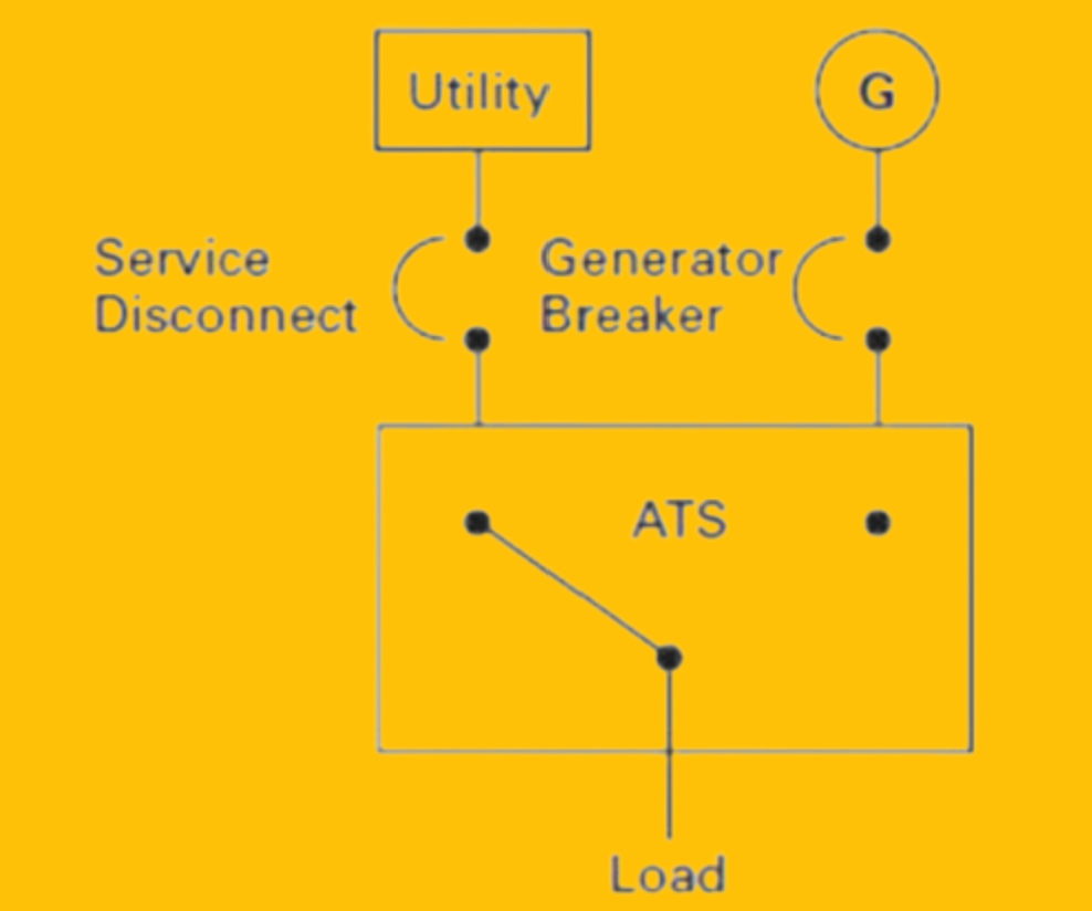
Determine the application for the ATS, such as utility-to-generator (Utility-Gen), generator-to-generator (Gen-Gen), or utility-to-utility (Utility-Utility). The application will dictate the type of ATS needed.
2. Service Entrance vs. Non-Service Entrance:
Decide whether the ATS will serve as a service-entrance switch, which connects to the utility service entrance, or a non-service-entrance switch, used for internal load distribution.
3. Switch Type:
Choose the appropriate switch type based on your requirements. Options include Transfer Switches, which transfer power between sources, and Bypass Isolation Switches, which provide redundancy and maintenance capabilities.
4. Transition Type:
Determine the transition type needed—open, closed, or non-automatic. The transition type impacts how the switch transfers power between sources.
5. Grounding Schemes:
Select the grounding scheme that aligns with your system’s requirements, whether it’s separately derived or non-separately derived grounding.
6. Switching Capacity:
Decide whether a 4-pole or 3-pole ATS is required. 4-pole switches are necessary for certain grounding and safety considerations, as mentioned earlier.
7. Switch Positions:
Consider the number of switch positions (2-positions, 3-positions) needed. 3-positions can be beneficial for load shedding and managing stored energy loads.
8. Cable Sizes and Entry Requirements:
Determine whether the ATS requires top entry or bottom entry for cables and ensure it accommodates the cable sizes used in your system.
9. Enclosures:
Select an appropriate enclosure type (e.g., NEMA Type 1, 3R, 4, 4x, 12) based on the environmental conditions and protection requirements of the installation site.
10. Voltage and Frequency:
Ensure that the ATS is rated for the voltage and frequency of your electrical system (e.g., 600VAC, 480VAC, 50Hz, 60Hz).
11. Current Rating:
Determine the required current rating of the ATS (e.g., 3000A, 2000A, 800A) to handle the load demands of your system.
12. Fault Current Capability:
Consider the fault current capability (WCR) needed to protect the ATS and the connected equipment in the event of a fault (e.g., 65kA, 85kA, 100kA).
13. Codes and Standards:
Ensure that the ATS complies with relevant codes and standards, including UL/CSA, NFPA, NEMA, ISO, EN, or any other applicable regulations in your region.
By carefully considering these factors, you can choose the right ATS for your specific application, ensuring reliable and safe power transfer between sources.
FAQs about Automatic Transfer Switch:
What is the purpose of a transfer switch?
What is the function of a Transfer Switch?
What are Different Types of Transfer Switches?
2. Non-Automatic Transfer Switch.
3. Manual Transfer Switch.
4. Service Entrance Rated Transfer Switch
5. Bypass Isolation Transfer Switch
What is main difference Two Position vs. Three Position Switches?
Three Position Switches are used for Good choice for switches requiring:
Delayed Transition.
Load shed – won’t transfer to “dead” source.
What is difference between 3-Pole Vs. 4-Pole Automatic Transfer Switch?
Only one neutral/ground connection is allowed on any neutral bus at a given time.
Ground fault sensors must be positioned downstream (or on the load side) of the bonding connection.
To adhere to both of these rules when connected to either the normal or the emergency power source, a 4-pole transfer switch is required. This configuration allows for the proper switching of the neutral, ensuring compliance with the specified rules and accurate ground fault sensing.
Codes and Standards for Automatic Transfer Switch
Automatic transfer switches must follow to various codes and standards to ensure their safe and reliable operation. Some of the key codes and standards relevant to automatic transfer switches include:
- NFPA 70, National Electrical Code (NEC): This code covers the installation and use of electrical equipment and systems, including automatic transfer switches. It provides guidelines for safe and compliant electrical installations and includes specific articles related to emergency and standby power systems (Articles 700, 701, 702, and 708).
- NFPA 110, Level 1, Type 10: NFPA 110 is a standard for Emergency and Standby Power Systems. While this standard primarily addresses the entire emergency power system, including generators and transfer switches, it sets important requirements for the design and operation of automatic transfer switches within these systems.
- NFPA 99, Standard for Health Care Facilities: NFPA 99 is specifically applicable to healthcare facilities and outlines requirements for the electrical systems in these settings. Automatic transfer switches used in healthcare facilities must meet the standards outlined in NFPA 99 to ensure patient safety and uninterrupted power supply.
- UL 1008: Underwriters Laboratories (UL) 1008 is a leading safety standard specifically for transfer switch equipment. It outlines stringent testing requirements to verify the safety and performance of transfer switches. Some of the tests included in UL 1008 are the temperature rise test, dielectric voltage-withstand test, overload test, contact opening test, endurance test, short-circuit test, and more. These tests help ensure that transfer switches can safely and reliably transfer power between sources.
Read Also: Solar Power Plant Construction and Working [PDF]
To Download PDF of this article please EnterEnterCtrlCtrl+Ctrl+P