The Fall-of-Potential Method, also known as the three-point grounding measurement method, is a technique used to measure the electrical resistance of a grounding system or electrode, typically an earth electrode. This method is commonly employed to assess the effectiveness of grounding systems in electrical installations, ensuring that they meet safety and performance standards.
What is Fall of Potential (Basic Principle)?
The Fall of Potential Method is a precise technique for testing the resistance of a grounding electrode. It based on Ohm’s law, which states that when a potential difference is applied between two points, it causes a flow of charge, and the resistance encountered opposes this flow. According to Ohm’s law:
Current (I) = Potential Difference (V) / Resistance (R), or
I (amperes) = V (volts) / R (ohms).
This fundamental law led to the concept of resistance, measured in ohms. When we apply a potential difference to any conductor and measure the resulting current, we can determine the resistance of the conductor by dividing the voltage drop by the current, expressed as:
R = V / I.
Where R=Resistance, V= Voltage, I=Current
This equation is the definition of electrical resistance.
However, in the context of the Fall of Potential Method, the resistance is not constant, as illustrated in Figure 1. Therefore, a graphical approach is used to determine the electrode’s resistance.
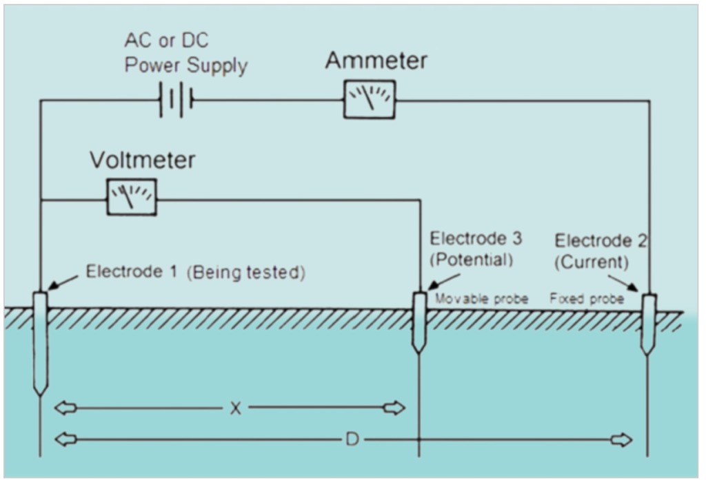
The Fall-of-Potential Method involves passing AC or DC current between the electrode under test (electrode 1) and a fixed electrode (electrode 2). Simultaneously, it measures the voltage drop between electrode 1 and a movable electrode (electrode 3). While commercial measuring equipment typically employs ground rods instead of hemispheric electrodes, the principles of earth resistance behavior align with those studied for hemispheric electrodes.
To measure the current in the circuit, an ammeter is used, which has low resistance. To measure the voltage drop, a voltmeter with high resistance is connected. Both instruments have minimal impact on the measurement results.
The resistance value at the position of electrode 3 is determined by calculating the ratio of the measured voltage drop to the circulating current.
Modern earth testing equipment performs these calculations internally and directly displays the resistance in ohms. In specific cases, such as in transmission and distribution applications with extensive distances (D), specialized techniques and instrumentation may be necessary.
The Fall-of-Potential Method is a robust and reliable approach to assess grounding electrode resistance, ensuring electrical safety and compliance with industry standards.
Fall of Potential Method
The most common method for measuring earth ground resistance is the “Fall of Potential Method.” To obtain accurate measurements using this method, it’s essential to adhere to a precise procedure. This process can be time-consuming and relies on factors such as the grounding system’s layout, the terrain, and other variables. Cutting corners during measurement can lead to errors. This paper outlines the general procedure for a single earth grounding point and introduces a modified approach using a current probe for testing ground resistance in systems with multiple earth grounding points, such as those used for lightning protection or power poles and transmission pylons.
To measure the earth ground resistance of a single ground electrode at point “E,” a current is directed to flow toward E by inserting an auxiliary test probe (H) into the ground at a specific distance away from the E electrode. H is then connected to a current source. In this scenario, the ground resistance test meter acts as the current source, generating an alternating current. An electrical circuit is established between H and E, with current flowing through the ground between them. Along this path, electrical potentials are created due to the resistance. An auxiliary test probe (S) is inserted into the ground between E and H to measure electrical potential (voltage). Voltage varies along the path between E and H, with the maximum voltage occurring at E and zero at H. Hence, the term “Fall of Potential Method” is used because the voltage potential decreases as the S probe moves away from E towards H. By recording the voltage at S, we can calculate the earth resistance using the voltage and current values.
Experience has shown that the ground point E must be a sufficient distance away from the auxiliary probe H. The reason for this relates to the electrical performance of an electrode or probe inserted into the ground. A longer and deeper electrode can facilitate a greater current flow to and from it than a short, shallow probe. Current flow in the ground is mainly electrolytic, and higher moisture levels promote better electron flow. Additionally, a long electrode has more contact with the surrounding ground than a short one, enabling a greater volume of electron flow. When measuring voltage near an electrode, it’s observed that the voltage gradient increases as one gets closer to the electrode E. As one moves further away from E, the voltage gradient levels off and eventually falls to zero. The gradient increases again as S approaches the H probe. To avoid confusion, it’s important to note that we are discussing voltage gradient, not the actual voltage.
In the diagram provided, observe the voltage gradient curves near the electrodes and a plateau, or zero-gradient area, between them. It is within this zero-gradient area that we aim to measure voltage to determine ground resistance. It’s crucial that the two electrodes are far enough apart to prevent the gradients around them from overlapping or interfering with each other, ensuring a zero voltage gradient area can be measured. Typically, the distance between probes E and H is accepted to be 25 or 50 meters apart to establish a zero voltage gradient. Depending on soil and terrain conditions, a longer distance may be necessary. Experience has shown that the first voltage measurement taken by S should be made at approximately 62% of the distance between E and H. To confirm the existence of a zero gradient region, the voltage probe S is moved a few meters closer to the tested ground point E and then closer to the auxiliary current probe H. At least three tests are required to verify the zero voltage gradient zone’s presence and, consequently, the measurement’s accuracy. Depending on conditions, multiple measurements may be needed, which is why this process can be time-consuming. We can consider the measurements valid when three voltage results are the same or very close, typically within a few percent of each other.
Multiple Ground Points and Fall of Potential Method with Current Probe
In situations where a grounding system involves multiple ground points, such as building structures with complex grounding networks, conducting accurate measurements following the conventional Fall of Potential Method can be challenging. This is due to the interconnected nature of these grounding points, making it difficult to isolate and measure each point individually, which can impact measurement accuracy.
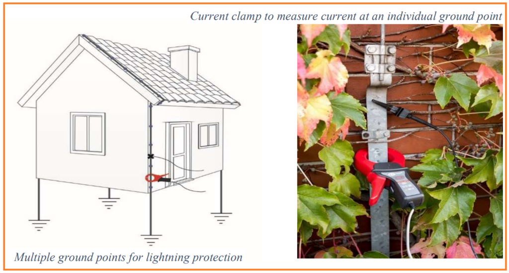
Consider the example of a building with a lightning conductor on the roof, featuring four interconnected ground termination points, as shown above. The traditional Fall of Potential Method relies on applying a test current from a source to a single ground point to calculate resistance. However, in scenarios with multiple paths to ground like this one, the test current will naturally flow to all four ground points situated at the building corners. This presents a challenge in terms of isolating and individually measuring each ground point while keeping them connected to the overall system. Temporarily disconnecting each ground point is often neither desirable nor practical.
To address this challenge, the Fall of Potential Method with Current Probe technique is employed. This method allows for the determination of the resistance of the entire grounding system without the need to disconnect multiple building ground connections. It accomplishes this by using a current probe that isolates and measures the current associated with a specific grounding electrode. Here’s the procedure:
- Place a current clamp around the ground conductor of interest within the building’s complex grounding network.
- Attach the E probe to the same conductor that the current clamp encircles.
- Position the H probe at a distance away from the current-carrying conductor.
- Conduct the measurement using the Fall of Potential Method by measuring the voltage gradient with the S probe.
- Rather than using the total current generated by the meter, calculate resistance based on the value of the current measured by the current probe.
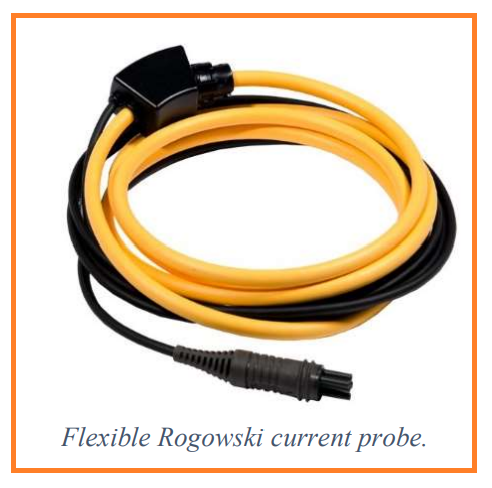
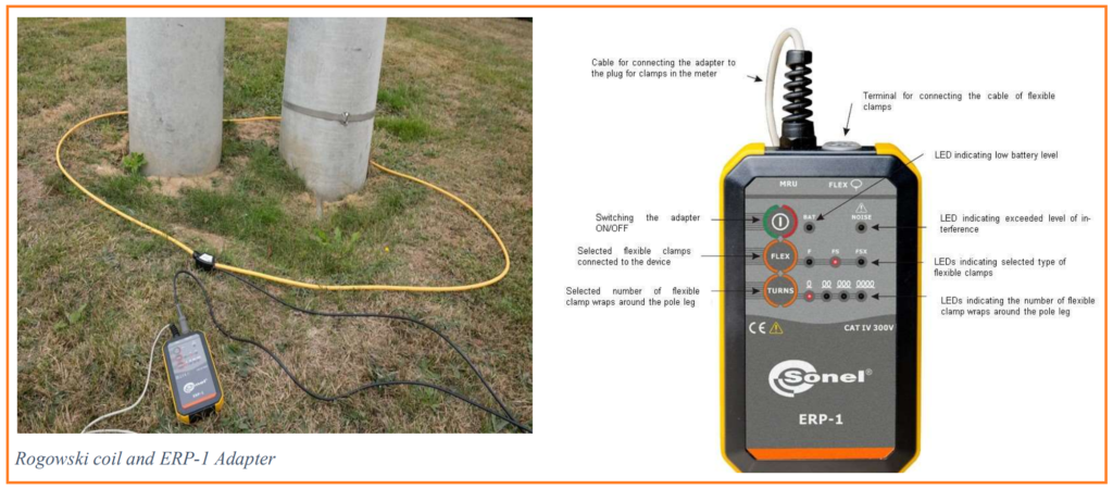
To perform the current measurement physically, access to the conductor is required, and the current probe is placed around it. In some situations, using a conventional current clamp may be challenging due to its rigidity and bulkiness, especially in confined spaces. In such cases, a flexible Rogowski-coil current probe can be employed as an alternative to ensure accurate measurements.
Fall of Potential Method with Current Probe for Power Poles and Pylons:
When assessing the ground resistance of power poles and transmission pylons, it’s essential to distinguish when they can be considered as single-point grounds and when they cannot. The classification is crucial for maintaining accurate measurements.
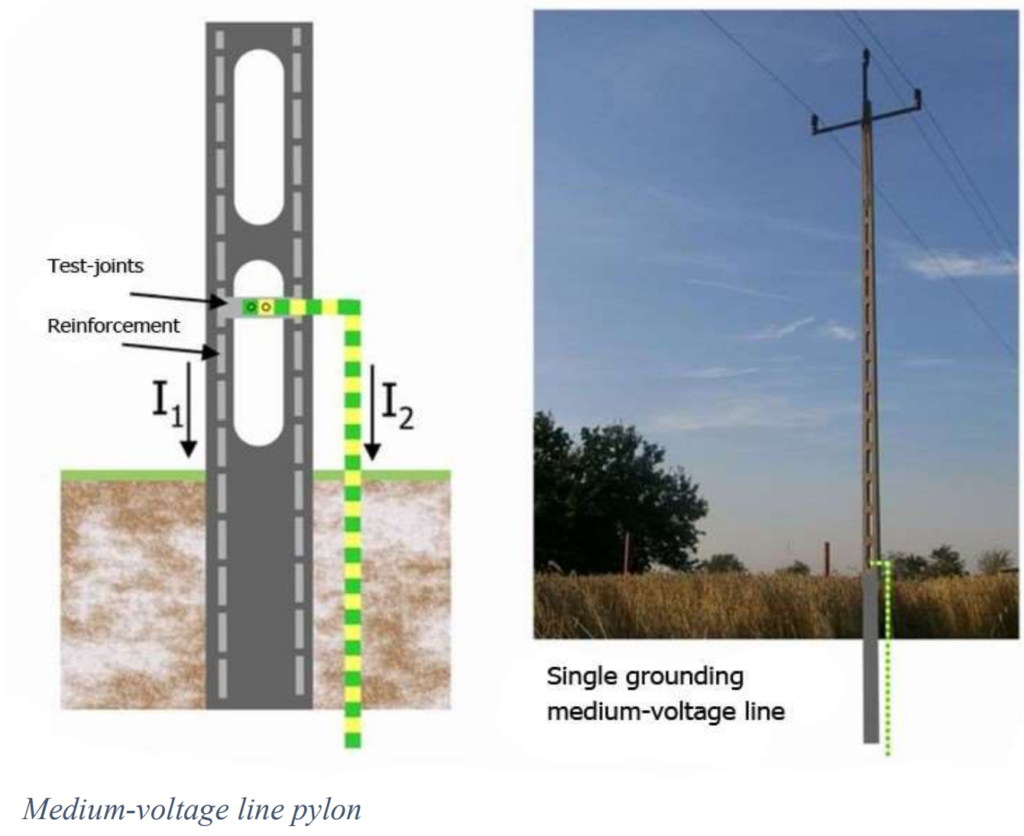
Let’s consider the example of a medium-voltage pylon, as shown here. Each pylon can be viewed as a single earth ground point, but this assumes that each pylon is not physically connected to its neighboring pylons. In this scenario, each pylon is bonded to a ground using a metal electrode, which is further connected to the internal reinforcement rebar inside the concrete structure. The concrete itself contains moisture, and the combination of water content and mineral salts in the concrete forms an electrolyte capable of conducting electrical current.
To perform the ground resistance test:
- Connect the E meter to the grounding electrode of the pylon.
- Position the H probe of the test meter at a distance away from the pylon.
- Follow the standard Fall of Potential Method, measuring the voltage gradient with the S probe.
In this case, most of the test current (I2) flows through the grounding electrode, while a fraction (I1) follows a parallel path through the concrete, although it is significantly smaller compared to (I2). Since there are no alternative paths to ground, the measured test current will be the sum of (I1) + (I2).
However, when testing ground resistance for low-voltage pylons, a different approach is necessary. While it may initially seem that each low-voltage pylon constitutes a single grounding point, the presence of multiple ground paths must be considered. Unlike the medium-voltage situation, where each pylon typically stands alone, low-voltage pylons in a row are often connected to their neighboring pylons via a fourth aerial Protective Earth Neutral (PEN) cable, which itself is grounded. Additionally, other pylons may be embedded directly in the ground.
The diagram below illustrates these multiple paths (Rx):
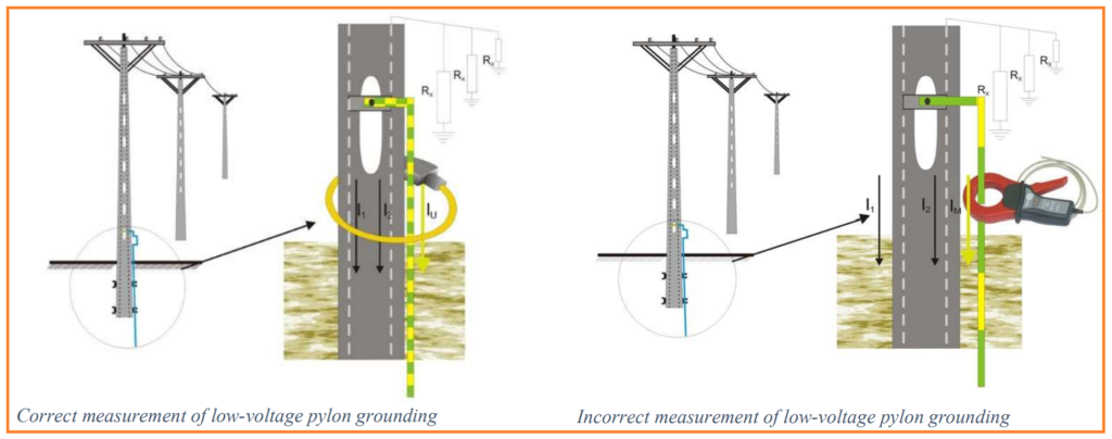
In this scenario, where multiple paths to ground exist, the Fall of Potential Method with Current Probe must be employed to ensure accurate measurements.
During a ground resistance test for structures like pylons and power poles, it’s important to recognize that the test current generated by the meter can follow multiple paths to ground. These paths may include traveling along the aerial PEN conductor to neighboring pylons, passing through the concrete structures of the pylons themselves, and running through the ground-bond electrode wire at each pylon.
If we attempt to measure the fall of potential and calculate resistance using the total current generated by the meter, which includes all these paths, we will obtain an incorrect and artificially low resistance calculation. This error occurs because the total current includes contributions from all these parallel paths, leading to an underestimated resistance value.
To ensure accurate ground resistance measurements, especially in scenarios where multiple ground paths are present, such as interconnected pylons, it is imperative to employ the current probe method. This method allows us to isolate and measure only the current associated with the specific pylon being tested, effectively ignoring the current flow through other paths.
By using the measured clamp current from the current probe, we obtain a resistance value that is higher but considerably more accurate. This approach takes into account the true resistance of the specific pylon of interest without interference from parallel ground paths, ensuring reliable test results.
To achieve the highest accuracy in measuring ground resistance, the current probe must encircle the entire pylon to capture the current flowing through its individual grounding electrode as well as through the concrete to the ground. Placing the current probe only around the electrode would not account for the current flowing in the concrete, even though it is relatively small compared to the electrode current, as previously described.
To facilitate this comprehensive measurement, specialized flexible Rogowski current probes have been developed by Sonel. These probes are designed to be thin and can extend up to 5 meters (16 ft.) in length. The key component enabling their operation is the Sonel ERP-1 adapter. This adapter comes with four FS probes, each 4 meters (13 ft.) long, as the standard configuration. Additionally, the adapter is compatible with other Sonel probe types, including type F, type FS (which offers higher sensitivity), and customized FSX (highly sensitive) probes. Users also have the flexibility to select the number of turns the probe makes around the pylon, with more turns increasing the probe’s sensitivity.
For measuring ground resistance at high-voltage steel pylons, the ERP-1 adapter proves to be a valuable tool for automating resistance calculations for all four legs of a steel pylon. Here’s the procedure for utilizing the ERP-1:
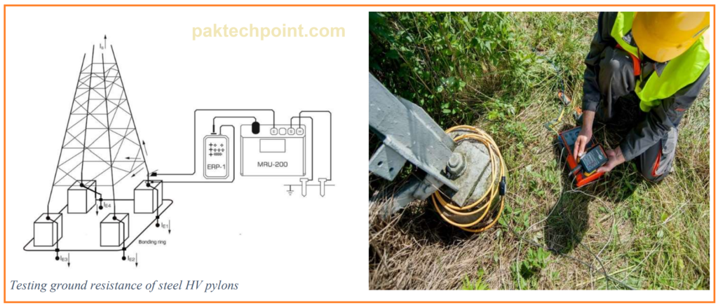
To measure the ground resistance of a high-voltage steel pylon effectively using the Fall of Potential Method with the Sonel MRU-200-GPS test meter and the ERP-1 adapter with Rogowski current probe, follow these steps:
- Place a Rogowski current probe around one leg of the steel pylon. Ensure that the arrow on the current probe, indicating the direction of current flow, is pointing down toward the ground. For increased sensitivity and accuracy, consider coiling the probe around the leg up to four times.
- Connect the ERP-1 module to the Sonel MRU-200-GPS test meter.
- On the ERP adapter, select the number of turns made by the current probe around the pylon.
- On the test meter, select the number of legs of the pylon you are testing (1-4).
- Connect the E probe to the first leg of the pylon.
- Position the H probe a suitable distance away from the pylon.
- Begin making voltage gradient measurements using the Fall of Potential Method. The initial measurements to establish the zero gradient may take the most time.
- Once the zero voltage gradient is established, move the current probe to the next leg of the pylon for the next measurement. Maintain the same polarity of the current probe (always pointing the arrow down), and keep the E connection on the first leg to account for the pylon’s resistance.
- Keep the meter electrode H and the S probe in fixed positions.
- Repeat this process for each leg of the pylon, making voltage gradient measurements.
- After completing the series of leg tests, the meter will display the earth ground resistance for the entire steel pylon.
The Sonel MRU-200 series of ground resistance testers offers the unique feature of automatically calculating the earth ground resistance for an entire steel pylon. Additionally, it can identify physical breakdown or corrosion of the bonding connector connected to the earth bonding ring of the pylon, which may result in high-resistance measurements. This capability sets the Sonel MRU-200 apart in the market for ground resistance testing.
FAQs about Fall of Potential Method
Q1: What is the Fall of Potential Method in ground resistance testing?
Q2: What equipment is typically required for performing the Fall of Potential Method?
1. A ground resistance test meter capable of generating an alternating current (AC) or direct current (DC) test current.
2. Grounding electrodes (E and H).
3. Test leads and cables.
4. Proper safety equipment and gear.
5. Optionally, a current probe for measuring the current in specific grounding electrodes.