This standard is a guide for use of variable area flowmeters (rotameters) in process plants and main keywords are Disadvantages of variable area flowmeter or Rotameter, Advantages of variable area flowmeter or Rotameter. Metering Tubes of variable area flowmeter.
Basic of Rotameter – What is Variable Area Flowmeter
- Rotameter is the most common type of variable area flowmeter and is used extensively throughout the industry to measure rate of flow. Various designs are available to provide local and remote indicating, recording, integrating, and alarming.
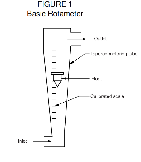
- Rotameter consists of a vertical tapered tube of annealed borosilicate glass, metal, or transparent plastic, with the smaller or inlet end at the bottom. As the fluid flow increases, a float is raised by the fluid to provide a larger annular area for passage of the fluid. The flow rate is indicated by the position of the float relative to a calibrated scale. See Figure 1.
- Depending upon the type of meter, tube, and float, rotameter is capable of measuring flow rates ranging from a minimum of approximately 0.05 mL per minute to a maximum of approximately 3,200 gpm of water, and a minimum of approximately 5 mL per minute to a maximum of approximately 13,000 scfm of air. Minimum measurable flow rates are usually around 10 percent of the maximum flow rates. The maximum flow rate provided by a specific meter is determined by the metering tube and float designs, fluid density and viscosity, and in addition for gases, the metering pressure and temperature.
- Design of rotameter shall be suitable for the required area classification and shall be in conformance with following standards.
a. NFPA 704M
b. NFPA 49
c. NFPA 325M
d. NFPA 30
e. NFPA 70
Metering Tubes of variable area flowmeter or Rotemeter
- Metering tubes are available in effective lengths from 40 to 600 mm. The most common scale lengths in industrial use are 250 mm for indicating meters (see Figure 6), 125 mm for metal-tube indicating and transmitting meters (see Figures 8, 9, and 10), and 40 to 150 mm for purge meters (see Figure 5).
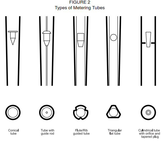
- Metering tubes may have smooth bores (conical metal, glass, or plastic tubes) or may have integral float guides (glass or plastic tubes). Tubes with integral guides are identified by the various manufacturers as ribbed, fluted, or triangular flat metering tubes. See Figure 2.
- Conical metering tubes require floats designed to be stable throughout the metering range, or floats whose horizontal movement is restricted by a guide rod. Meters with conical glass tubes are not suitable for metering opaque fluids.
- Flat, ribbed guides eliminate the problem of float stability, and floats can be designed to reduce the effects of fluid viscosity and density variations on calibration, and to provide low or high capacities. Meters with these types of tubes are usually suitable for metering opaque fluids.
Glass Metering Tubes
- Rotameters with toughened borosilicate glass metering tubes are used primarily for local indication of flow rate.
- Maximum operating pressures range from about 350 psig for the smallest diameter tubes ( inch inlet inside diameter) to 50 psig for the largest (3 inches inlet inside diameter). Because of the
unpredictable nature of glass and the susceptibility of the tubes to damage, operation at maximum rated pressures is not recommended. - Meters with glass tubes shall be shielded, or provided with enclosures having adequate venting area, or designed to ensure discharge of fluid and fragments in a direction that does not endanger personnel in the event of tube rupture. The shield or enclosure shall be designed to provide this protection up to at least 1 -1/2 times the maximum allowable working pressure of the meter. Meters with enclosures not meeting these requirements shall be vented by removing the back cover.
- For most services, toughened glass is neutral. However, glass metering tubes shall not be used to meter the following:
a. Hydrofluoric acid
b. Fluorine
c. Fluoride solutions
d. Strong alkaline solutions
e. Hot alkaline solutions
f. Hot, strong acids
g. Hot phosphoric acid containing fluorides
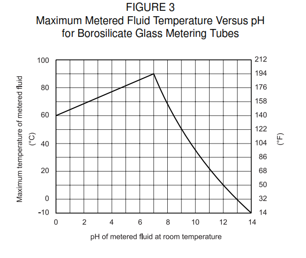
h. Hot water above 90°C (194°F) - Figure 3 shows suggested maximum metered fluid temperatures based upon pH at room temperature of the fluid.
Metal Metering Tubes
- Rotameters with metal metering tubes are used primarily where pneumatic or electric signal transmission is required, or for local indication where conditions preclude the use of glass metering tubes.
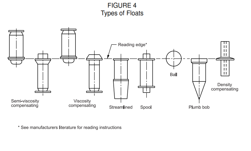
- Floats. Meter capacities can be modified by variations in float design and selection of float material. Basic designs include viscosity compensating, streamlined, density compensating, and ball floats. See
Figure 4. - Ball Floats. Simplest of the float designs are the ball floats, used primarily for low flow rates. Ball floats are common in small diameter tubes ( 1 /16 to 1 / 4 inch inlet inside diameter). They are sensitive to
changes in liquid and gas viscosities. - Streamlined Floats. Normally, streamlined floats are more economical because they provide the highest flow rate capacities in a given tube (meter) size. However, calibrations are affected by viscosity
variations in liquids. - Viscosity Compensating Floats. These floats are designed to prevent or minimize calibration shifts due to viscosity variations in the metered fluid.
- Density Compensating Floats. These floats are usually used in high accuracy meters for test or
calibration applications. - Rod-Guided Floats. Density compensating floats can be used in rod-guided meters with conical glass metering tubes.
Types of Rotameters
Numerous types of rotameters have been developed for different requirements. Rotameter accuracies vary depending upon the type of meter, the scale length, and the calibration procedure. Accuracies applyto flow rates from 10 to 100 percent of full scale reading. Accuracies for generally available rotameters arein Table I.
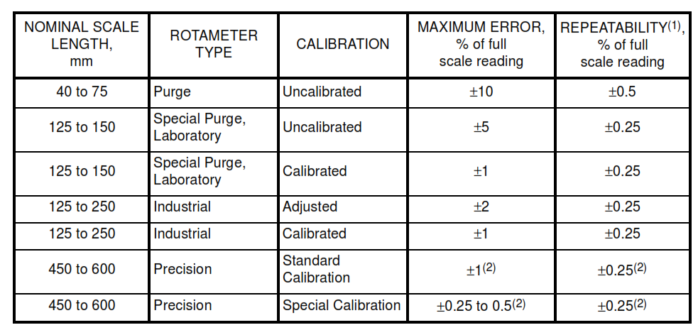
Notes:
(1) Repeatability (reproducibility) is the maximum variation in scale readings for repeated applications of a given flow rate.
(2) Percent of indicated flow rate.
Indicating Rotameters
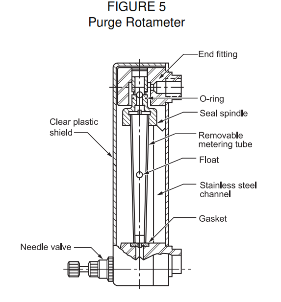
- Purge Rotameters (Figure 5). The term ‘purge rotameters’ refers to low-capacity meters of the type used to purge instrument impulse lines. Scale lengths vary from 40 to 75 mm with maximum capacities
ranging from about 0.1 to 30 gph water (1 to 120 scfh air). Meters are available either with borosilicate glass or clear acrylic metering tubes. Meters with integral check valves or flow control valves, or both, are available. - Special Purge Meters. These meters are suitable for the many applications where low flow rate meters with longer scale lengths and higher accuracies are required. Applications include bearing
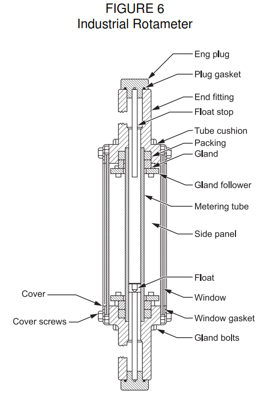
lubrication, cooling water, additives, mechanical seal flushing, analyzers, and chromatography. - Industrial Rotameters (Figure 6). These meters are provided with enclosures, and in some cases with shields. The meters range in size (metering tube inlet diameter) from 1/2 to 2 inches. Larger meters,
up to 4 inches, are available. Usually, either 125 or 250 mm scale lengths are available. - High-Accuracy Rotameters. The design features of these meters are similar to those of the industrialmeters but with scale lengths of 450 to 600 mm.
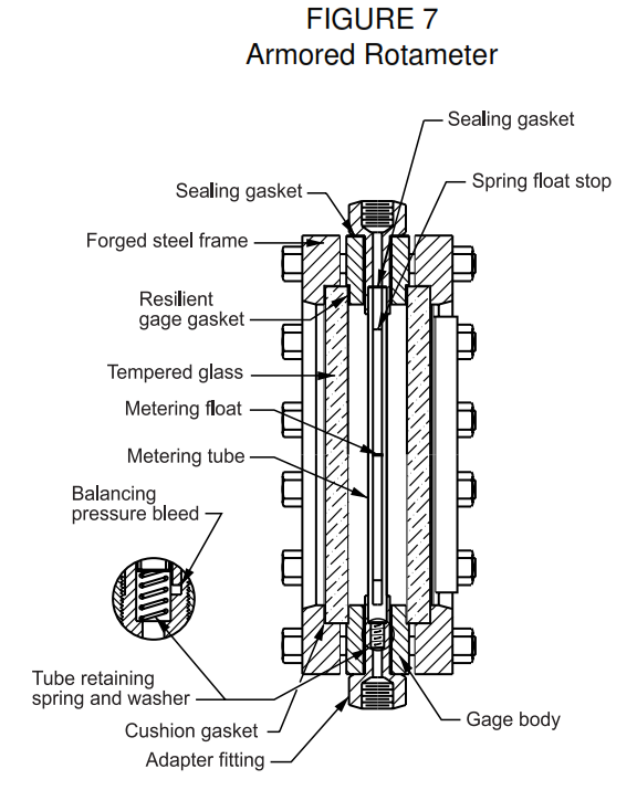
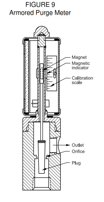
- High-Pressure (Armored) Rotameters (Figure 7). High-pressure meters utilizing glass metering tubes are confined to small sizes with tube inlet diameters ranging from 1/16 to 1/2 inch with scale lengths of 125, 150, and 250 mm. Tubes with integral float guides are installed in heavy steel or stainless steel bodies, and heavy steel cover plates are bolted on the front and rear as retainers for heavy tempered borosilicate gage glasses. To prevent the glass metering tube from being overpressured, a small internal vent equalizes the tube internal and external pressure. Accuracies are the same as those for industrial meters.
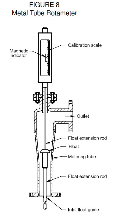
- Metal Tube Indicating Rotameters (Figure 8). These meters are employed where pressure, temperature, or fluid characteristics preclude the use of glass metering tubes. The float has upper and
lower extension guide rods to center the float in the fluid stream. An encased cylindrical magnet is attached to the top of the upper extension rod and extends into an enclosed metal tube above the meter. A short metal sleeve around the metal tube tracks the magnetic float extension as it moves with the float when the flow rate varies. An alternative design replaces the upper metal tube with a high-pressure borosilicate gage glass, so the end of the upper float extension guide rod can be viewed directly. - Usually, metal tube armored purge meters are the orifice and tapered plug type (see Figure 2), with flow rate indicated by a metal sleeve magnetically coupled to a magnet encapsulated in the plug (float) or plug extension. The meters can be supplied with switches for actuating relays.
Multiple Function Rotameters
Where functions, for example recording, integrating, alarming, or transmitting are required in addition to local indicating, two basic types of rotameters are available, the extension meter and the through-flow
meter.
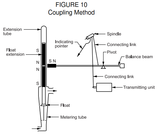
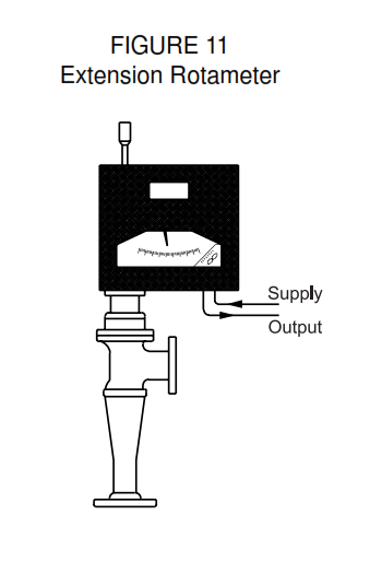
- Extension Rotameters (Figure 11). These meters are similar to metal tube indicating rotameters, except that external magnets enclosed in a housing track the float movement and actuate the desired
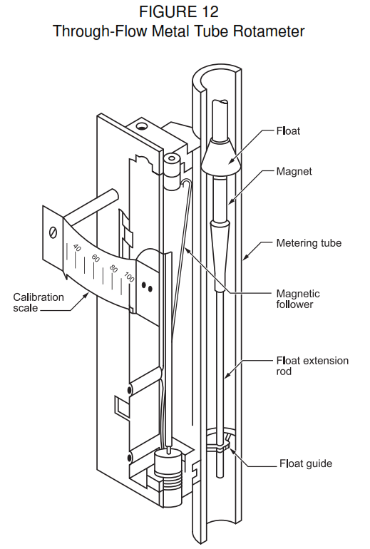
functions. Figure 10 illustrates one method of coupling the float for local indication and pneumatic signal transmission. - Through-Flow Rotameters (Figure 12). The through-flow meter has the magnet in the body of the float with the float position sensor mounted at the side of the metering tube. With no stagnant pockets
where solids can collect, or where liquids can coagulate or crystallize, the through-flow meter is, in effect, an integral part of the pipeline. As such, it is self-cleaning and may be used to meter slurries, distillation column bottoms, dirty fluids, and viscous solutions. This meter requires careful handling because the float is easily damaged. Clearances between the float and tube are small, so fluids have to be clean. For local flow rate indication, the rotameter provides the lowest cost method up to and including the 2 inch metering tube. For larger line sizes, the shunt (bypass) rotameter, a combination of orifice plate and rotameter, provides the lowest cost method.
Advantages of variable area flowmeter or Rotameter
- Rotameters do not require external impulse or lead lines.
- Float position can be observed directly (glass metering tubes) or by means of magnetically coupled indicators (metal metering tubes).
- Meters with glass metering tubes permit inspection of the float and metered fluid.
- Scale graduations are usually linear and enable reasonably accurate measurement of flow rates as low as approximately 10 percent of maximum meter capacity.
- The linear relationship between float position and flow rate in transmitting rotameters permits use of linear charts on receiving instruments.
- When flow is pulsating, damping the float movement or averaging the scale readings provides a more accurate indication of actual average flow rate than averaging variable-head meter readings.
- Straightening vanes, or straight runs of pipe upstream or downstream of the meter, are not required.
- The pressure drop across the float is constant and relatively low. The remaining pressure drop through the meter body is similar to that developed in pipe and fittings and varies with flow rate.
- Small-capacity changes can be made by simple changes in the float weight. Larger changes can be made by substituting standard floats or metering tubes.
- The inherent flow-through nature of the meter tends to make it self-cleaning and permits handling slurries and dirty fluids in some designs.
- Steam-jacketed meters are available for freeze protection.
- Almost any chemically active or corrosive fluid can be metered due to available materials of construction.
Disadvantages of variable area flowmeter or Rotameter
- Glass metering tubes are fragile and subject to breakage from external blows, hydraulic and thermal shock, and excessive strain induced by improper tightening of stuffing boxes, or by misaligned piping.
- Glass metering tubes are eroded by undissolved solids, particularly in the vicinity of the float where maximum fluid velocities are encountered.
- Glass metering tubes are unsuitable for metering alkaline solutions, including very dilute solutions at elevated temperatures.
- The metering edge of floats in metering tubes with integral guides is subject to wear, particularly when the flow is pulsating.
- Good accuracy with high-viscosity fluids requires special calibration, particularly where the Reynolds number may decrease to the 5,000 to 10,000 region.
- Dirty or opaque fluids require float extensions to make indication possible, causing meter to lose some of its simplicity. Metal tube meters with magnetically coupled indicators are more expensive.
- Transmitter floats and floats with indicating extensions are relatively heavy and usually limit the use of these meters to flow rates above 1 gpm of water and 5 scfm of air, or equivalent.
- Foreign particles can accumulate on the side of the tube and on the float, hence affecting the accuracy of the meter. They can also block the flow.
Precautions of variable area flowmeter or Rotemeter
- Floats used for metering gases have a minimum operating pressure limit that varies with meter size and float weight. Operating below this pressure will cause the float to bounce violently and break the
metering tube, if glass, or damage the float or meter. - When installing the meter, piping shall be aligned carefully to avoid strain and possibly breakage of the metering tube if glass.
- Hydraulic and thermal shock shall be avoided when using meters with glass metering tubes.
- Use of a start-up screen upstream of the meter shall be considered, to stop foreign objects.
- Each installation shall be analyzed to make certain that failure of associated equipment, operating errors, or closing upstream and down-stream valves to seal the section of pipe in which the rotameter is installed will not result in subjecting the meter to pressures in excess of its rating. If excessive pressures can occur, the meter shall be protected by a properly sized pressure relief device. Also, consideration should be given to the need for a readily accessible shutoff valve, a flow limiting orifice, or automatic controls to shut down the pressure source.
- When starting flow through a meter, the valve shall be opened slowly to avoid surges that may damage the float decouple or break the metering tube if glass, or decouple the follow-up from the float
extension. - To maintain accuracy, the float shall be replaced if visibly damaged.
- An increase in friction level between float and metering tube guides, or float extension guide and extension tube, due to dirt deposits, erosion, or corrosion will affect accuracy and may not be apparent.
- Freeze protection may be required.
- Meters employing floats with magnetic extensions shall not be used for fluids containing magnetic particles. The particles will accumulate at the poles of the magnets, resulting in increased friction or
sticking. Where fluids are considered free of magnetic particles, this condition can develop due to magnetic particles chipped or eroded from equipment in the system. - Variations in viscosity of metered liquids may cause unacceptable measurement errors. Some manufacturers can provide flow coefficient curves for standard float and tube combinations. Coefficient
curves shall be requested when meters are purchased. - When metering fluids which may affect glass metering tubes by chemical action or erosion, the tubes should be inspected periodically until a predictable service life can be established. The first signs of attack may appear at the inlet and outlet ends of the tubes. If the flow rate is constant and the float remains at one position during operation, attack will usually begin in the vicinity of the float.