The purpose of this Method Statement is to describe the sequence of operation and precautions to be observed to ensure the installation of 13.8kV, 4.16kV, & 0.48kV Cable bus is performed safely, efficiently and in accordance with International Standard Specifications. The Method Statement is intended to provide general application guidance and established control during preparation and installation.
CABLE BUS INSTALLATION METHOD STATEMENT (13.8kV, 4.16kV & 0.48Kv)
Required Tools and Equipment
- Electric Drill
- Drill Bits
- Hacksaw
- Drill Hammer
- Socket Wrench
- Expansion Anchors
- Stake-bed Truck
- Crane
- Welding Machine
- Man Lift
- Forklift
- Megger Tester
- Other Relevant Tools
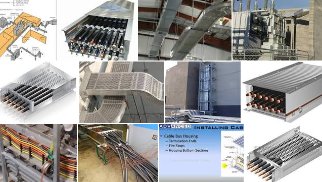
Cable bus Installation
- Verify the accessibility of the area of installation.
- Ensure that the transport of this equipment from the laydown yard to the Substation should be thoroughly planned.
- From a trailer / truck using a suitable equipment down the cable bus to the cleared staging area.
- The cable bus shall be un-crated in the presence of Company representatives.
- Identify the components (type, materials, dimensions) as are based on the current designs.
- After the inspection has been made, the cable bus equipment shall be lifted near the area of installation.
- Check the position and the level of the lay out elements. (Transformer connections, Switchgears, etc.).
- Layout the actual equipment dimension measurement on the location where the equipment is to be installed.
- Marked the exact location of the Cable bus external and internal supports.
- Having confirmed the locations of supports install the cable bus support as per the IFC and manufacturer recommendation drawings.
- Disassembly the cable bus materials.
- Select the suitable components.
- Using a suitable crane, carefully lift the cable bus components and installed it on the support.
- Complete the assembly and install the cable bus fixing supports.
- Terminate the Cable bus to the corresponding dedicated Transformer and Switchgear.
- A visual inspection on all sealing’s and on tightness of bolts has to be carried out at the assembled cable bus.
- Having confirm the integrity of the cable bus assemblies and terminations, install and fix the covers.
- Cable bus enter in Substation through cut outs shall be sealed with the approved flanges and sealing materials.
- Bond and ground the Cable bus equipment in accordance with SAES-P-111 Para. 9.5
- As per 16-SAMSS-520 section 6:
- Cablebus used outdoors (shaded) shall be suitable for continues use in an ambient temperature of 50 o Cablebus used indoors shall be suitable for continues use in an ambient temperature 50 oC (non-air-conditioned locations), or 35 oC (air-conditioned locations)
- Cable bus used outdoors shall be suitable for a wind load of 100 km/hour unless otherwise specified on the Data Sheet.
- Cable bus enclosures construction shall be as per 16-SAMSS-520 section 8.1.
- Cable bus conductor supports shall be as per NEC 370.4 (D).
- Cable bus enclosure grounding shall be as per 16-SAMSS-520 section 8.4 and cable bus installation shall be grounded and bonded in accordance with article 250 of NEC, excluding 250.86 exception no. 2 as per NEC 370.9.
- Cablebus equipment connections constructions shall be as per 16-SAMSS-520 section 8.5.
- Cablebus Wall/Floor penetrations constructions shall be as per 16-SAMSS-520 section 8.6.
- Cablebus support and extension through walls and floors shall be as per NEC 370.6
- Cablebus field installation and termination shall be as per 16-SAMSS-520 section 8.7.
- Cablebus fittings shall be as per NEC370.7
- Cablebus nameplates shall be as per 16-SAMSS-520 section 8.8 and NEC 370.10
- As per SAES-P-116 section 14:
-
- Cablebus shall be used with power transformers if the forced cooled site rating of the transformer is greater than 1200 A.
- Cablebus shall not be used with pad-mounted transformers. If the cablebus is penetrating a wall with a fire rating, the cablebus shall be supplied with a listed internal fire barrier and vapour barrier. The damper/ barrier shall have the same, or greater, fire rating as the wall through which it passes.
-
- Pre-installation Activities
- Ensure that all relevant documents have been approved by Saudi Aramco prior to commencing installation, and that the latest revisions of IFC drawings, specifications including approved procedures are disseminated to concerned personnel who will carry out the work.
- Ensure that all Materials and other miscellaneous materials are available, to be transported from warehouse / laydown area to the work area and complies with the project specifications.
- Check materials for damage before transporting to the work area. All materials of doubtful condition or quality shall be immediately segregated from the job site.
- Check that all materials shall be clean, new and unused.
- Check the manufacturer’s name, trade name or other acceptable marking whereby the organization responsible for the product can be readily identified.
- Check the availability of the product installation instruction.
- Check that the materials shall be traceable from the manufacturer and supplier through delivery, storage, fabrication, erection, installation, repair modification and used.
- Electrical materials shall be identified using tags, stamps, colour coding, stencils or labels.
- Check materials for damage before transporting to the work area. All materials of doubtful condition or quality shall be immediately segregated from the jobsite. A NCR must be raised and the materials shall not be used and send to quarantine.
- Ensure material receiving inspection has been carried out before materials transporting to the work location.
- Secure work permit for Cablebus installation and other associated works if required.
- Ensure Safety Barrier is erected at designated work areas.
- For high elevation installation, ensure adequate PPE, scaffold ladders and access ways are available at the work location.
- Plan the work area with separate storage, work and waste disposal locations, to avoid congestion and enable systematic installation.