LAW OF MAGNETISM

LAW OF MAGNETISM

When an external magnetic field is applied to ferromagnetic materials, the magnetic domains align parallel to the applied fields. These domains are very small, but larger than the atoms of the material. It is the interchange action between atoms and the alignment of the magnetic domains that are the cause of increased flux density. As the magnetizing force increases, the aligned
domains increase in volumetric steps. This incremental increase is detectable, and is often referred to as the barkhausen effect. When all the domains in a material are aligned, the material is said to be magnetically saturated.

Read more

MAGNETS AND MAGNETIC FIELDS

MAGNETS AND MAGNETIC FIELDS

The theory of magnetic fields indicates that an object is magnetized when part or all of its atomic elements have their north and south poles aligned. Earth’s magnetic field is produced by the rotation and movement of the planet’s molten iron core. This produces a magnetic field that is relatively stable in direction.

Because of this stable magnetic field, early explorers could reliably use compasses built with lodestone, charged iron needles and other naturally magnetic materials. The Earth itself can be considered a bar magnet because of its two poles. Quite frequently, the magnetic field surrounding the Earth strongly magnetizes large ferromagnetic objects that lie aligned with the Earth’s poles for periods of time.
The directions of the Earth’s magnetic field may be changed by major geologic events over many thousands of years. There are many local magnetic anomalies having higher levels of magnetic attraction near the Earth’s surface. It is thought that these may be caused by iron or nickel deposits.

Read more

CAPABILITIES OF MAGNETIC PARTICLE TESTING PERSONNEL QUALIFICATION

CAPABILITIES OF MAGNETIC PARTICLE TESTING

Magnetic particle testing can reveal surface discontinuities, including those too small or too tight to be seen with the unaided eye. Magnetic particle indications form on an object’s surface in the area of a discontinuity and show the location and approximate size of the discontinuity. Magnetic particle tests can also reveal discontinuities that are slightly below the surface.
There are limits to this ability to locate subsurface discontinuities. These are determined by the discontinuity’s depth, size, type and shape; the strength of the applied field; and the type of current used.

In some cases, special techniques or equipment can improve the test’s ability to detect subsurface discontinuities. Magnetic particle testing cannot be used on nonmagnetic
materials, including glass, ceramics, plastics or such common metals as aluminum, magnesium, copper and austenitic stainless steel alloys. In addition, there are certain positional limitations: a magnetic field is directional, and for best results must be oriented perpendicular to the discontinuity. This generally requires two complete magnetizing operations to detect discontinuities parallel and perpendicular to the test object’s axis. Objects with large cross
sections require a very high current to generate a magnetic field adequate for magnetic particle tests. A final limitation is that a demagnetization procedure is usually required following the
magnetic particle process.

Read more
What is Magnetic Particle Testing

Magnetic particle testing can detect both production discontinuities, such as seams, laps, grinding cracks and quenching cracks, and inservice damage, such as fatigue and overload cracks.
Next to visual testing, it is one of the most cost effective methods of nondestructive testing. Its major difficulty is that the test object must be magnetizable. Magnetic particle technology depends on the property of magnetism occurring in certain elements referred to as ferromagnetic materials.Magnetic particle testing is a relatively simple test method that can be applied to finished articles, billets, hot rolled bars, castings and forgings. It can also be used to confirm that the processing operations, such as heat treatment, machining and grinding, did not cause discontinuities. There are many differing modes of electrical current that are used in magnetic particle testing.

Read more

STRIP CLADDING SUBMERGED ARC STRIP CLADDING ELECTROSLAG STRIP CLADDING

strip cladding

INTRODUCTION TO STRIP CLADDING

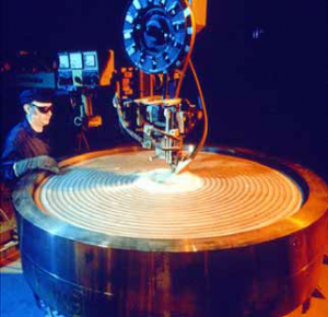
Cladding is a welding process in which a material with desired properties is deposited on the surface of a base material. The common C/Mn or low alloyed inexpensive base metal has mainly a load carrying function. The deposited sophisticated material imparts surface properties such as corrosion resistance, wear resistance, etc., to the substrate.
To the manufacturer of pressure vessels, surfacing techniques are getting more and more important. Components reach sizes such that their fabrication calls upon the use of clad materials.
There are different processes to obtain a clad material :
– clad plates produced by rolling which are mostly only available in standardised dimensions and grades
– explosion clad plates
– clad plates made by welding
Among all the welding processes submerged arc and electroslag strip cladding offer maximum deposition rate, better bead characteristics and trouble free operation using unsophisticated welding equipment. Strip cladding is also a very flexible process covering a very wide range of applicable materials.
The fact that in general it is used to clad finish shaped components eliminates the eventual problems arising with cold or hot forming.
The principle of strip cladding was developed about 70 years ago (the first patent was granted in the USA around 1920) but in Europe the process retained detailed attention when the nuclear industry started (late 1950’s).
The nuclear power industry needed a method whereby thick- wall pressure vessels could be given a corrosion resistant inner surface.
Several modifications of submerged-arc welding with strip have been developed mainly with a view to further increase surfacing capacity.
In the first part of this paper the SUBMERGED ARC STRIP CLADDING process will be discussed, in the second part the ELECTROSLAG STRIP CLADDING technique will be described. The influence of the working parameters will be given and the main advantages and limitations will be listed.

Read more

error: Content is Protected.