1. Purpose
2. Scope
3. Conflict and Deviation
4. Applicable Documents
5. Responsibility
6. Manpower
7. Tools & Equipment
8. Methods / Procedures
9. Quality Control
10 . Safety Precaution
11. Attachment
1.0 PURPOSE
1.1 This Procedure / method statement will serve as a minimum guideline to carry out the installation of centrifugal compressor activities at buildings, plants and refineries.
2.0 SCOPE
This method statement will cover the minimum requirements for installation of centrifugal compressor to be applied at the site for buildings, plants and refineries.
3.0 CONFLICTS AND DEVIATION
In the event of any conflict between this procedure and Saudi Aramco Standards, the latter shall prevail.
4.0 APPLICABLE DOCUMENTS
4.1 Project Specification and Standards
4.1 .1 S-000-1 630-003 Material and Equipment Protection Program at work site
4.1.2 S-000-1520-103 Handling Procedure
4.1.3 S-000-1640-005 Procedure for Work Release Between Disciplines
4.1 .4 S-000-1520-102 Non-Conformity Control Procedure
4.1.5 S-000-1520-101 Field Quality Control Procedure
4.1.6 S-000-1650-001 Safety Execution Plan
4.1 .7 FWBS CODE (5000) Equipment Installation
4.2 ARAMCO Specification and Standards
4.2.1 SAEP-302 Instruction for obtaining a waiver of mandatory Saudi Aramco Engineering Requirements.
4.2.2 SAES-Q-010 Cement Based Non-shrink Grout For Structural and Equipment Grouting.
4.2.3 SAES-L-350 Construction of Plant Piping.
4.2.4 SAES-K-402 Centrifugal Compressors.
4.2.5 SAIC-M-2006 Inspection of Support Foundation prior to Structural and Equipment Installation.
4.2.6 SAIC-K-2002 Receiving Inspection of Centrifugal Compressor.
4.2.7 SAIC-K-2003 Storage, Handling and Preservation of Centrifugal and Reciprocating Gas Compressors.
4.2.8 SAIC-K-2004 Mounting Plate Installation and Leveling for Compressor.
4.2.9 SAIC-K-2005 Inspection of Auxiliary Piping Installation for Compressor.
4.2.10 SAIC-K-2008 Final Compressor / Driver Alignment.
4.2.11 01-SAMSS-017 Auxiliary Piping for Mechanical Equipment.
4.2.12 Gl-7.025 Heavy Equipment Operator Testing and Certification.
4.2.13 Gl-7.028 Crane Lift-types & Procedure.
4.2.14 Gl-7.029 Rigging Hardware Requirement.
4.2.15 PIP Process Industry Practices.
4.2.16 Related Vendor’s Installation and Maintenance Manuals and/or Specification.
4.3 Inspection and Test Plan / Method Statement
4.3.1 SATIP-K-402-01 Centrifugal Gas Compressor for Process Air or Gas Service.
4.3.2 SATIP-Q-010 Cement Based Non Shrink Grouting.
4.3.3 SATIP-P-113 Medium Voltage Induction and Synchronous Motors (Up to Nameplate Voltage 13.2 kV).
4.3.4 SATIP-J-902-03 Factory Assembled (Packaged) Auxiliary Instrumentation System.
4.3.5 SATIP-P-515 Factory Assembled (Packaged) Auxiliary Electrical System.
4.3.6 SATIP-G-115 Lubrication, Shaft Sealing & Oil Systems (Rotating Equipment).
4.3.7 SATIP-W-011 Welding of On-Plot Piping .
4.4 Latest Revision of the following documents shall be used.
4.4.1 Vendor Drawing.
4.4.2 Foundation Drawing.
4.4.3 Equipment Details.
4.5 Saudi ARAMCO Safety, Health and Environmental Standard.
4.5.1 Construction Safety Manual.
4.5.2 General Instructions (G.l’s) at the work site.
5.0 RESPONSIBILITY
5.1 Construction Manager shall be responsible for all HSE matters. Analyze and schedule all construction activities with his department to include manpower and equipment line up as well as other possible resources required for the successful implementation of the construction work activities. Study all aspects of work procedure as per Technical Scope of Work and Saudi Aramco Standards.
5.2 Mechanical Superintendent/Supervisor shall review all necessary documents for the installation works I his area to include, technical scope of work, specification, bill of quantities, planned milestone dates and construction procedure in support to his Mechanical Foreman. He shall monitor the availability of materials in accordance with the schedules and construction analysis. He shall directly report to the Construction Manager. Coordinate with other disciplines to visualize possible conflicts in the drawings as well as in the schedules to provide other options in preventing unnecessary delays and obstructions.
5.3 Mechanical Foreman shall be responsible for the direct work supervision at site and ensure the work is performed in accordance with Technical Scope of Work and latest approved for construction drawings. He shall monitor the availability of materials / line with his required schedule.
5.4 QC Inspector shall be responsible for monitoring and inspection of the work and ensure that the work is performed in accordance with Technical Scope of Work and Saudi Aramco Standards.
5.5 Field Supervisor shall be responsible for monitoring safety aspects and ensuring that the work is done in accordance with Safety Standard Procedure and Saudi Aramco Construction Safety Manual. He shall discuss with the workers the characteristics of related materials and status of work are giving reminders as an additional point to work safely.
6.0 MANPOWER
6.1 QC Inspector shall be directly reporting to QC Supervisor in accordance to Schedule “Q”.
6.2 Safety Engineer
6.3 The Millwright Supervisor shall control the overall activity of equipment installation. The basic manpower under him shall consist but not limited to the following:
6.3.1 Foreman Millwright.
6.3.2 Millwright.
6.3.3 Mechanical Fitters.
6.3. 4 Rigger (Aramco Certified).
6.3.5 Crane Operator (Aramco Certified).
6.3. 6 Masons / Carpenters.
6.3.7 Truck Driver.
6.3.8 Helper.
6.3.9 Welder.
6.3.10 Surveyor.
7.0 TOOLS AND EQUIPMENT
7.1 Tools and equipment needed should be in calibrated, in good condition and must be checked by competent person and respective Supervisor prior to use in the plant. These include but not limited to:
7.1.1 Calibrated engineering level with calibration certificate.
7.1.2 Corrective wrenches all required range.
7.1.3 Crane.
7.1.4 Certified slings and hoists.
7.1.5 Chipping hammer / Bush hammer.
7. 1.6 Welding Machine.
7. 1.7 Compressor.
7.1.8 Calibrated Alignment and Leveling tools (dial indicator, precision master level, other measuring equipment); Final shaft alignment shall be as per Vendor’s recommended method.
7.1.9 Low-height rampack jacks.
7. 1. 10 Chain block..
7.1.11 Vendor supplied tools, if any.
7.1.12 Rubber mallet.
7.1.13 Calibrated Torque Wrenches.
7.1.14 Calibrated Micro level.
7.1.15 Grout mixer.
7.1.16 Hydrojack with pump.
7.1. 17 Calibrated Vibration meter.
7.1.18 Calibrated Temperature meter.
7. 1.19 Calibrated Flow meter (digital type) as required.
7. 1.20 Filler gauge.
7.1 .21 Magnetic stand for dial gauges.
7. 1.22 Calibrated micrometer.
8.0 CENTRIFUGAL COMPRESSOR INSTALLATION PROCEDURE METHODS
8.1 Jobsite Receiving and Inspection:
8. 1.1 Upon withdrawal, all requirements of storage at site shall be incorporate into the site preservation plan and adhered to in all respects and receipt of equipment from warehouse. Receiving inspection shall be conducted immediately as per applicable SATIP and SAIC-K-2002 to verify compliance and latest revision of vendors drawing.
8. 1.2 Record of inspection shall be documented as per applicable SATIP and SAIC (material rece iving inspection); findings and deviations shall be documented in Quality Control Inspection Report (QCIR) and Non Conformance Report (NCR).
8.2 Equipment Preservation / Protection:
8.2.1 Vendor’s/Manufacturer’s recommendation for equipment preservation shall be followed applicable provision to S-000-1630-003 (Material and Equipment Protection Program).
8.2.2 Equipment Rust Preservation shall be done using applicable vendor/manufacturer’s documents.
8.2.3 When the equipment arrived at site, shop preservation shall be checked. Where necessary damage to preservation shall be rectified without delay.
8.2.4 Special care must be taken when handling parts that have threads to prevent them from flaw or damaging.
8.2.5 When cleaning, never use wire brush. Use only clean sponges or paper towel.
8.2.6 Clean parts with cleaning oil unless otherwise specified. Make sure to remove all rust preventives from parts completely.
8.2.7 Never use fibrous rags to clean inside of machine, oil water reservoir, oil and water filters, etc. Fibers will re main inside and when operating the will clog oil paths and cause bearing and seal troubles.
8.2.8 Be sure to place cover all opening on machine, reservoir, piping and etc. which dust or foreign materials may enter inside.
8.2.9 Follow preservation procedure of rotary equipment for lubrication of bearings during turning.
8.2.10 All oil-lubricated bearings hosing, seal, stuffing box, hydraulic equipment and gear cases are filled with manufacturer approved oil as per Sec. 3.2 of SAES-K-402, further refe rred to API 686, Para. 2.3.17 (as per V-21 58-2 11-0014 Para. 4.3).
8.3 Preparatory Works
8.3.1 Secure work permit and other applicable approved documents prior to work commence.
8.3.2 Tools and equipment shall be made operational and available for use. Ensure tools are color-coded accordingly.
8.3.3 Conduct lifting study and get approved lifting plan in accordance with GI 7.028 for re quired cases.
8.3.4 Prior to the arrival of equipment on site, shall review the manufacturer’s req uirements of this specification regarding on site storage of the equipment. These requirements shall be incorporated to site preservation plan and adhere to in all respects.
8.3.5 Install barricades to confine the area for authorized personnel only.
8.4 Foundation Plan:
8.4.1 Confirm acceptance and turnover of civil works foundation/pedestals with a signed copy of work release notice.
8.4.2 After receiving foundation release note, the fol lowing points shall be checked with the latest relevant drawing.
8.4.2.1 Foundation Check
o Measure scribed lines laid out on foundation.
8.4.2.2 Visual Examination
o Confirm the degree of dryness, curing condition and curing period of concrete
8.4.2.3 Dimensional Examination
o Prepare independent bench mark on the table top corner for elevation and level reference. It is essential point for compressor work.
8.4.3 Trace centerlines of foundation bolt holes with reference to gridlines. Check verticality/plumbness of anchor bolt.
8.4.4 Clean the surface thoroughly by blowing with oil-free from air compressor.
8.4.5 Centerlines lost due to chipping operations will retrace anew.
8.4.6 Anchor bolts shall be protected properly to avoid damages during chipping/padding work and keep it up to the equipment installation.
8.4.7 The elevation of the chipped top foundations shall allow for at least 50mm of grout under the base plate as per SAES-Q-005 Concrete Foundation.
8.4.8 The equipment shall be cleaned and free of laitance, oil or grease.
8.4.9 In case that leveling jack bolts are not provided on the equipment base frame, it shall be perform using straight liners on both side of bolts basically.
8.4.10 Laitance shall be removed from the surface of the foundation and boxes by chipping to ensure good adherences of padding and grout materials to the surface preparation.
8.5 Setting of Pad:
8.5.1 Padding plates and liners shall be machined flat parallel and can allow the weight of the compressor equipment to be installed.
8.5.2 Padding plate material shall be in accordance with ASTM A36 Gr. C, D or equivalent.
8.5.3 Padding plate shall be hot dip galvanized in accordance with ASTM A 123 or coated with zinc rich epoxy primer in APCS-1C of SAES-H-101V as applicable.
8.5.4 Preparation
o The compressive strength of the grout shall be a minimum of 35Mpa (5000 psi) at 28 days of age.
8.5.5 Preparation of Pads
o Liners of compressor skid base (leveling plates) shall be supplied by Vendor.
8.5.6 Position of Pads
o Compressor skid base pad shall be located under the jack bolts of compressor base plate.
8.5.7 Height and level of pad
o Adjust the height and level of pads on the basis of the lower surface of base plate.
o Compressor base plate height and level of pad.

Setting of Pad
o Cleaning and wetting of foundation.
o Water the setting area 24 hours before setting the pads and keep the setting area wet. Thoroughly remove the remaining water in the setting area with sponges just before setting the pads.
o Mix a ratio of 2.5 ltrs of water per 25 kgs. of Masterflow 526 or equivalent non shrink grout.
o Place the dry pack grout within 5 minutes of mixing or until the desired consistency is achieved. Place grout by hand and ram (damp-pack).
o To facilitate grout movement, compressed the grout during pouring. 12 mm minimum thickness is recommended.
o Setting of liner.
8.5.8 Equipment supports are provided with stainless steel (AISI Standard Type 300) shims minimum 3mm thickness:
o The maximum shim stack height shall not exceed 12mm thick.
o Only one 3mm (0.125in) or thicker shim per mounting foot is allowed.
o All shims are to straddle hold down bolts and jackscrews.
o Maximum number of shims under any equipment support foot is five (5) (API 617 para. 3.3.1.2.2 / API 618 para. 7.5.3.3 / API 686 chapter 7, para 5.4.2.1).
8.5.9 All mounting surfaces that are not to be grouted shall be coated with a rust preventive immediately after machining.
8.5.10 After finishing padding work, following points shall be checked.
o Position of center and elevation line of foundation
o Elevation and position of pads
o Cleanliness of concrete surface
o Condition of anchor bolts.
8.6 Lifting of Centrifugal Compressor
8.6.1 Prepare lifting location where the crane will be located and positioned.
8.6.2 Prepare and set all rigging accessories according to arrangement.
8.6.3 Checked wind condition, lift shall not proceed when wind velocity is greater than required of crane.
8.6.4 Stabilized ground area where crane will be located and positioned. Crane mats shall be provided in accordance to finding s of soil bearing pressure.
8.6.5 Crane lift and rigging requirement shall refer to GI 7 .025.
8.6.6 Rigging plans should be approved. The skid equipment or complicated equipment must be leveled for lifting by the use of proper sling wire or lifting gear. Spreader bar shall be used on lifting of compressor.
8.6.7 The equipment shall be lifted by lifting lugs, lifting trunnion and not by nozzles. Lifting points and lugs shall be clearly identified on the equipment or equipment package. The recommended lifting arrangement shall be identified on boxed equipment.
8.6.8 For base-plate or skid-mounted, only use lift points on base plate or skid. Do not use the machinery as a lift point unless approved by the manufacturer.
8.6.9 Equipments shall be protected by wooden blocks, rubber or other suitable material that will prevent equipment from damages caused by sling wires.
8.6.10 Install centrifugal compressors on top of the foundation as per approved lifting plan.
8.6.1 1 Equipment shall be set and aligned at the proper position, elevation, levelness and perpendicularity in accordance with the drawing.
8.7 Temporary setting of Compressor base plate:
8.7.1 Temporary Setting of base plate
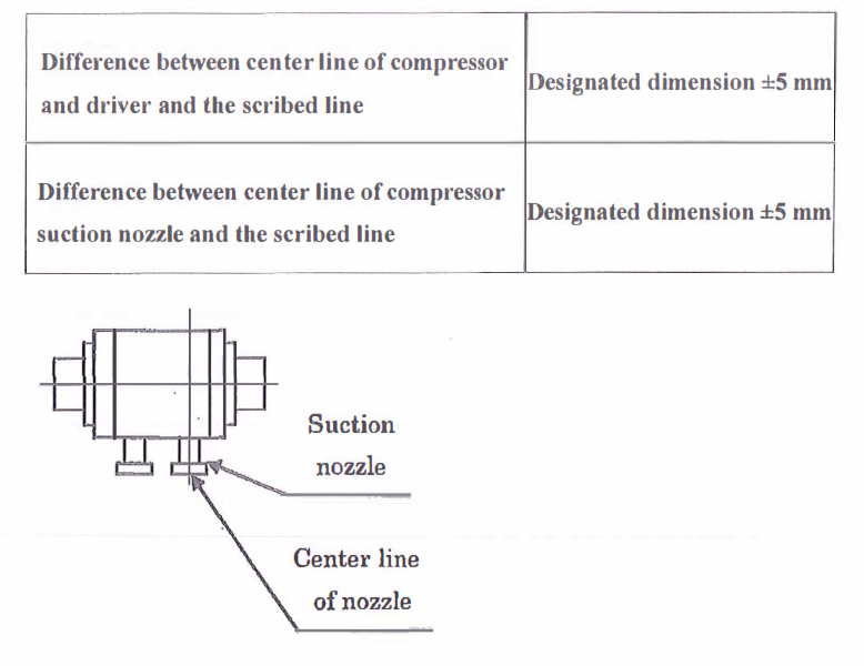
o Align the centerline of compressor with scribed line.
o Align the centerline of compressor suction nozzle with scribed line.
o Remove scratches and burrs on the bottom surface of base plate.
o Set the base plate temporarily with the anchor bolts.
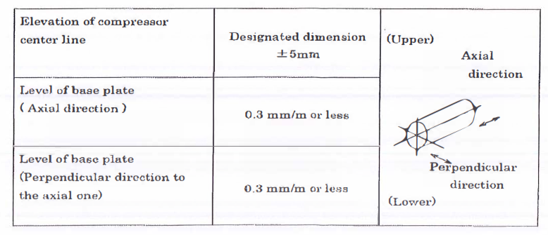
8.7.2 Elevation of compressor
o Check the elevation of compressor with optical alignment “Y-level” according to the bench mark and scribed line.
o Adjust the elevation of compressor with the jackscrews.
8.7.3 Level of base plate
o Measure the level of base plate with precision level.
o Adjust the level of base plate with the leveling screws until it reaches the vendor requirement.
8.7.4 Tolerance
o Elevation and Level
8.7.5 Position
8.8 Preparation for alignment
8.8.1 Remove the special tool on driver side to fix the rotor, the bolt and the cover.
8.8.2 Rust prevention shall be carried out to the interior part, and each rotor is fixed by the special jig under shipment. Before alignment, remove the special jig to the fix rotor.
o Remove the special tool (transport support) to fix the rotor, the bolt, and the cover.
8.8.3 Disassembly, washing and re-assemble shall be carried out, referring to “OPERATION AND MAINTENANCE MANUAL FOR CENTRIFUGAL COMPRESSOR”.
8.9 Coupling Alignment procedure
8.9.1 General
o Coupling hubs shall be installed in accordance with the equipment arrangement drawing and instructions including design pull-up and final hub position on the shaft. Coupling hub run-out readings shall be taken at the coupling hub rim machined surfaces perpendicular to the centerline of rotation. Readings shall also be taken on the face of coupling hub machined surfaces as far as practical from the shaft center of rotation. Installed coupling hubs shall have 0.05 mm (2mils) or fewer total indicated run-out (TIR) or the equipments vendor requirements, whichever are more restrictive. This limitation applies
both to the coupling rim as well as to the coupling face.
o Coupling alignment between compressor, gear and driver shall be carried out on the basis of compressor.
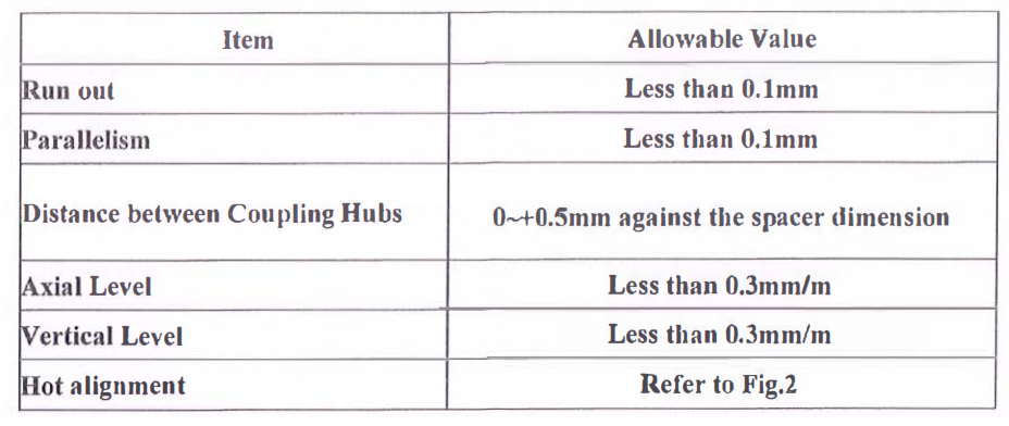
o Measure the run out, parallelism, distance and level between equipment.
o Consider the deflection of the jig and the value of hot alignment.
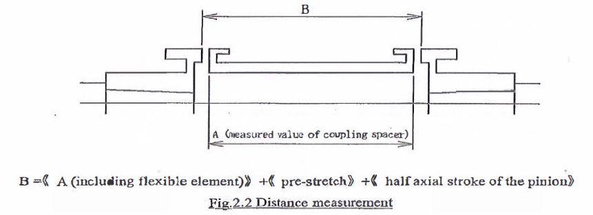
8.9.2 Distance between coupling
o Measure and record the thrust bearing clearance of gear shaft, and confirm the clearance within tolerance. Refer to instruction manual of gear.
o Measure and record the total axial stroke of the pinion.
o Push the pinion shaft to the driver side.
o Measure the distance between the coupling hubs by using of telescopic gauge.
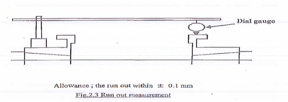
8.9.3 Adjustment of the run out
o Set lever type dial gauge on the shaft of compressor. Make the coupling hub of driver with a pencil at 90° intervals and measure run out, rotating the shaft compressor. Adjust the run out within ±0.1 mm of the calculated run out. The calculated run out means the run out considering the value of hot alignment.
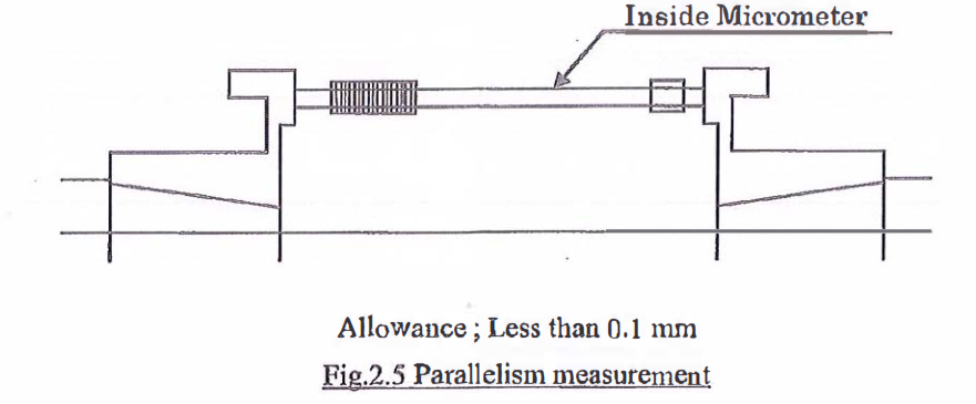
8.9.4 Adjustment of parallelism between coupling faces
o Measure the parallelism between coupling faces with inside micrometer at diffe rent four points.
o Adjust the run out and parallelism to fall within the allowable value.
o Adjustment of parallelism is to be carried out by jack bolts.
8.9.5 Alignment check procedure
o Rotate the measure rotor and the non-measured rotor by 90° in the same direction, and measure the run out and the parallelism.
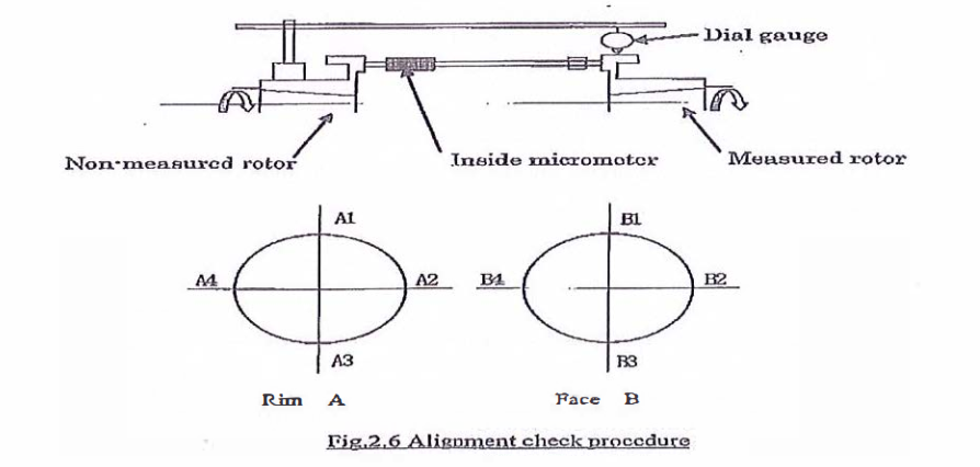
o Calculate the offset value by putting the measured values into the following equations.
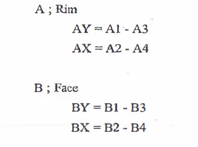
8.9.6 Adjustment
o Adjust the run out and parallelism unit. All the offset value (AX, AY, BX AND BY) meet the allowable values.
o Keep the thickness of all the equipment liners shall have the same value as possible.
o Adjustment of turbines shall refer to “OPERATION AND MAINTENANCE MANUAL OF MOTOR”.
o At the final stage, tighten the anchor bolts tightly at specified torque.
8.10 Final check of alignment
8.10.1 Final check of alignment shall be done in the condition that the compressor, suction piping and discharge piping have been installed.
8.1 0.2 If the measured value does not meet the allowable values, adjust the alignment until the value is within the allowable value.
o If the alignment value is over the allowable values, adjust the alignment of the driver and or gear unit.
8.11 Setting of Auxiliary Equipment
8.11.1 The installation of auxiliary equipment shall be done according to following procedure based on foundation drawing, general arrangement drawing and each equipment drawing or manuals
o Setting of oil console on the foundation
o Setting of other auxiliary equipment (seal gas unit, rundown tank, etc.)
8.12 Grouting
8.12.1 Prior to grouting of compressor, shaft alignment between compressor and gear box, gear box to motor (driver) shall be confirmed by vendor representative and approved.
8.12.2 Non-Shrink Grout. Following items shall be consider before grouting execution:
o Grout shall be mixed as per Grout Manufacturer’s instructions.
o Foundation preparation shall be in accordance with the grout manufacturer’s written instructions.
o Concrete foundations shall be cured for a minimum of 7 days before surface preparation for grouting.
o Laitance, oil-soaked or damaged concrete shall be removed down to sound concrete by chipping to the level of sound fractured aggregate or to a minimum of the top 2inch (50mm) of the concrete.
o All dust and loose particles shall be removed with clean, dry, oil free compressed air.
o Grout formwork, where req uired, shall be constructed with adequate strength, rigidity and req uired dimensions to permit grout placement and avoid leakage.
o Concrete surfaces in contact with the grout shall be saturated with clean water for 24 hours before grout placement. The surface shall be damp but free from standing water.
o Joints in the grout shall be located as shown in the drawings or as recommended by the manufacturer.
o Minimum grout gap shall be re ferred to the vendors drawing. It will be minimum 2″ to allow proper flowability of grout mortar during grouting.
o All screw (anchor bolt thread, jack screw) shall be tapped prior to grouting.
o Grout shall be placed in only one direction to prevent trapping air; Grouting shall be quick and continuous to avoid segregation, bleeding or premature initial set.
o Re-tempering of grout by adding water after stiffening is not permitted.
o If the grout is placed through grout holes, it shall be placed from one hole continuously until the grout has passed a second hole. A liquid head pressure shall be maintained at the first access hole until a head pressure is established at the second hole and continued in a similar fashion until the next hole. A “hopper” should be constructed to allow a pressure head sufficient to enable grout to flow to the full width of the pour. The form should be fixed with the top sloping away from the base plate at a 45° angle to form a slope down which the grout can be poured.
o Grout shall be mixed, placed and cured in accordance with manufacturer’s written requirements. The contractor shall read, understand and comply with the manufacturer’s instructions as printed on each unit.
o The grout shall be cut back to the lower edge of the base plate by 45° angle unless otherwise indicated.
8.1 2.3 After grouting works the following items shall be considered:
o The grout shall be checked for voids after the grout has cured. Any voids shall be filled according to grout manufacturer’s recommendation.
o After the void grout has cured, the base plate shall be re-checked to ensure that all voids are filled with grout. Any voids still exists shall be rectified.
o Exposed expansion joints shall be sealed with the grout manufacturer’s recommended sealant.
o The final level of the grout is flush with the top horizontal chamfer edges built into the formwork.
o Refer to the detailed void repair method described below using the Aramco Approved material for void repair (Nitomortar TC 2000):
• Surface Preparation
All concrete and mortar substrate must be sound, clean and free from oil, grease and surface contaminants. All loose materials and surface laitance must be removed. Clean the concrete surface using grinder. The prepared substrate should be thoroughly clean and blown with oil free air compressor to remove dust and any particles produced during the surface preparation.
• Mixing
The entire contents of the hardener can should be added to the base container and mixed thoroughly until a uniform color and consistency are obtained, taking particular care to scrape the sides and bottom of the containers.
• Application
Apply the mix Nitomortar TC2000 to the prepared substrate by spatula, filling knife or steel float, tight trowelling onto the substrate to ensure positive adhesion and that all blow-holes and defects are completely filled to produce a smooth even fin ish. Application thickness will vary with profile and alignment of substrate.
Where application of multiple layers is required, this can be accomplished by applying the additional layer between 2 to 8 hours at 25°C after the first layer application. This time should be reduced at higher temperature. Beyond this open time abrade the surface of Nitomortar TC2000 with sandpaper, and then remove the dust generated using clean rags. Alternatively the first layer of Nitomortar TC2000 may be “scratch keyed” whilst wet to provide mechanical key for subsequent layers.
• Finishing
Any ridges left by the trowel can be brushed out while the material is still wet or ground down with a carborundum stone before over-coating .
8.12.4 Grouting shall be performed after pre-alignment inspection as per SATIP-K-402-01 sequence of steps.
8.13 Installation of Auxiliary Piping
8.13.1 Auxiliary piping shall be inspected as per SAIC-K-2002 during receiving inspection.
8.1 3.2 All piping components are re-assembled/installed in their respective locations as shown in the P&ID (ie. piping, removable pipe spools, valves, vents, drains, spectacle plates, blinds, flange spacers, etc.)
8.1 3.3 All in-line equipment and instruments are installed in their respective locations as shown in the P&ID (ie. strainer, flow meter, orifice fitting, pressure indicators, temperature indicators, etc.
o For piping over 3-inch NPS and connected to equipment, flange alignment shall be with the following limits.
• Vertical bolt hole offset: ±2.4mm
• Horizontal bolt hole offset: ±2.4mm
• Rotational offset ±2.4mm
• Flange face tilt across diameter: 0.025mm/25mm (0.001 inch/inch) of flange outside diameter up to a maximum of 0.672mm (0.030inch) and 0.254mm (0.010inch) for all flanges with an outside diameter less than 10 inches.
• Flange face separation, gasket thickness: +1 .6mm
• Combination of vertical, horizontal and rotational offset: ±3.2mm
Note: Above tolerances may be exceeded if piping analysis per SAES-L-120 shows that loads and moments exerted are within the manufacturer’s limits for the machinery/equipment nozzle: (SAES-L-350 para. 9.5)
Any vendor provided pipe welding shall be conducted with approved welding procedure.
8.14 Driver Installation
8.14.1 Install drivers as per drawing or vendor’s req uirements
8.15 Control and instrumentation
8.15.1 Refer to SATIP-J-902-03 for Auxiliary Instrumentation Systems Installation.
8.16 Skid Mounted Auxiliary Electrical System Installation
8.16.1 Refe r to SATIP-P-515-01 for Auxiliary Electrical Systems Installation
8.17 (Lube & Seal Oil) Lubrication, Shaft Sealing & Control Oil System
8.17.1 All components of the Lubrication Skid shall be installed in conformance with the approved P&ID.
8.1 7.2 All piping connections for the lube and seal oil system shall be terminated in a flanged connection at the edge of the base plate.
8.17.3 The system layout is such that all system components including locally mounted indicators, switches, controllers, transmitters, etc., are easily accessible for maintenance purposes.
8.17.4 Indicators throughout the system are easily legible from the sides of the console.
8.17.5 Piping layout is such as to ensure maximum accessibility to all system components.
8.1 7.6 Lube/seal oil piping field joint will be welded with approved welding procedure.
8.17.7 During field piping installation, any pipe opening shall be sealed to avoid contamination from dust or sand. All pipe spools shall be inspected by QC Inspector for its cleanliness prior to connection to the Compressor.
8.17 .8 All instrumentation and controls re quiring an electrical supply shall be wired to terminal boxes.
8.1 7.9 Terminal boxes may be included on the gauge board or may be mounted on edge of the console, to facilitate ease of installing field wiring.
8.17.10 For systems which include accumulators, availability of a suitable charge gas at site is verified. Unless the vendor recommends otherwise, nitrogen is used for charging accumulators.
8.17.11 Oil or barrier fluid systems are installed parallel to the longitudinal side of the main equipment base plate and confirm not obstructing accessibility to the main equipment for maintenance/operation.
8.17.12 Reservoir installation elevation ensures the proper drainage of the oil return piping.
8.17.13 System is being flushed on site in accordance with SAES-G-1 16, use SAIC-G20-16 as reference or Vendor Manufacturer’s Procedure.
8.17.14 Demisters in accordance with API STD 614 option 2A-12d are equipped in closed loop compressor installations.
8.17.15 Pumps and drivers are mounted on a machined surface (API STD 614, Chapter 2, para 4.4.32).
8.17.16 Oil pump and driver pads are machined to allow for the installation of stainless steel shims; shim packs, at least 3mm (1/8inch) thick, shall be placed under the feet of each component (API STD 614, Chapter 2, para. 4.4.32).
8.18 Insulation / Cladding (by others)
8.19 Final compressor/drive alignment
8.19.1 Alignment is within the manufacturer’s tolerances before piping and conduit are attached. Pipe strain checks are as per manufacturer’s procedures. Alignment is within the manufacturer’s tolerances after pipe and conduit attached. Refer to API 686, chapter 7, para. 5.4.5 for details.)
8.19.2 Alignment Tolerances; (Axial Spacing Tolerances)
o For flexible element couplings, the coupling spacer gap length or distance between shaft ends (DBSE) shall be set as specified on the construction package data sheet or general arrangement drawing or within ±0.50mm (±20mils) unless a closer tolerance is specified by the vendor. Refer to API 686, para. 5.4 for details.
o The axial tolerance for DBSE or spacer gap length of equipment trains with gear or elastomeric couplings shall be set as required by the coupling or machinery vendor. The DBSE or space gap length shown
on equipment arrangement drawing or coupling vendor’s drawings shall be held within 1.00 mm (±40 mils) unless a closer tolerance is specified. Refer to API 686 para. 5.4 for details.
8.19.3 Shim Requirements
o The movable machines have a minimum of 3.0 mm (1/8 inch) thick stainless steel shim packs under each support foot. Shim packs are not thicker than 12mm (0.5in) nor contain more than 5 shims. Refer to API 686 para 5.4.2.2 for details.
o The use of tapered shim packs, laminated or peelable shims, brass shims, aluminum shims, plastic shims and shims thinner than 0.05mm (2mils) is not permitted. Refe r to API 686 para 5.4.2.2 for details.
o Unless otherwise specified by the user, it is not acceptable to cut shims from rolled shim stock. Shims shall have cut outs approximately 6mm (0.25in) larger than the diameter of any vertical jack bolts. Refer to API 686 para 5.4.2.2 for details.
o The total stack thickness and number of shims shall be recorded on the alignment data sheet. Measurement shall be recorded to the nearest 0.02mm (1 mil). For relatively large shims, the measurement will be in two or more locations to confirm the flatness requirement as per API 686, chapter 7, para 5.4.2.3.
8.19.4 Bolt and Bolt Clearance
o Hold down bolts is not bolt bound. Unless otherwise specified by the user, after final alignment the hold down bolt hole shall be reasonably centered base on visual examination. Refer to API 686, para 5.4.3.4 for more details.
o The equipment installation contractor shall record the following on the datasheets for special purpose equipment:
• The size of the hold down bolt
• Confirmation that the minimum clearance is acceptable
• The torque to tighten the bolt
• Refer to API 686, chapter 7, para 5.4.3.5
8.19.5 Soft Foot
o Soft foot check is done with piping disconnected on each equipment foot.
o Maximum permissible movement is 0.05mm (2mils) at each foot.
o Refer to API 686, chapter 7, para 5.4.4.1.
8.19.6 Reverse or Rim Face Alignment is performed while turning both shafts at the same time in the direction of rotation. For General Requirements and Cautionary Notes refer to API 686, chapter 7, para 4 .2.1 .2 see note 2.
8.19.7 Rim and Face Alignment with closed coupled machines or elastomeric coupling, the angularity shall not be greater than 0.03degress and the offset at the center of the coupling shall not exceed 0.02mm (1 mil) . Refer to API 686, para 5.4.6.5.
8.19.8 During alignment and pipe strain checks, the bearing bracket support foot (if existing) on single stage overhung pumps shall be loosened. The maximum amount of movement at the coupling during the tightening process shall be 0.05mm (2mils). Once this alignment is completed, for final acceptance, the bearing bracket support shall be shimmed and tightened . The maximum amount of movement at the coupling during the tightening of the bearing bracket support foot shall be 0.05mm (2mils). Refer to API 686, para 5.4.7.
8. 19.9 Final Alignment will be performed AFTER Hydrotest of piping and completion and acceptance of piping supports. NO COLD SPRING. See note 1 and attachments 1 & 2 of SAIC-K-2008. Complete checklist.
o Note: After final piping bolt-up, final shaft alignments are verified and all machinery is hand rotated to ensure that neither binding nor case distortion has occurred during piping installation. Piping spring hanger & spring support stops are installed during final shaft alignment checks. Refer to API 686, chapter 7, para 5.4.8 & 5.4.9.
8.20 Damages and Non-conformity
8.20.1 Any damages and defects and non-conformity found at site and lay down yard shall be reported immediately in accordance with (S-000-1520-102) Field Quality Control Procedure.
9.0 QUALITY CONTROL
9.1 QC Personnel shall be assigned to ensure the quality control and assurance requirement of the work.
9.2 Inspector shall be responsible to conduct all required inspections / documentations to ensure it complied with SAIC/SATIP.
9.3 Contractor has to utilize the applicable SAIC for every activity.
9.4 Mill test reports for the structural materials are furnished and verify to conform to the requirements of the applicable specifications.
9.5 Calibration shall be done as required for all machines and tools going to be used in the work in accordance with Schedule “Q”.
10.0 SAFETY PRECAUTION
10.1 Obtain the approval of the work permit and required applicable documents from the concerned Representative before starting any work.
10.2 Work execution shall be carried out in accordance with method statement and in compliance with Saudi Aramco GI 7.028, Crane Lifts; Types and Procedure.
10.3 Continuous monitoring and inspection shall be implemented to detect and correct unsafe practices while performing the work activities.
10.4 Provide warning sign and sufficient barricade on working area and only assigned personnel will be allowed in the area.
10.5 Machinery like grinding wheel cutter shall have a protection method.
10.6 All workers shall wear as a minimum PPE required below:
10.6.1 Safety Helmet
10.6.2 Safety Glasses
10.6.3 Safety Shoes
10.6.4 Gloves
10.6.5 Mask, if req uired to prevent inhalation of dust and welding gas
10.6.6 Ear plug, if req uired by conditions
10.7 Safety shall be requested and carried out in accordance with safety procedure.
10.8 All rigging equipment shall be in good condition and possess a valid certification from authorized certifying and inspection departments. In compliance with Saudi Aramco General Instructions GI 7.030 Inspection and Testing Requirements for Elevating/Lifting Equipment.
10.9 Field Supervisor shall monitor the work activities to help and to protect all assigned workers against exposure to safety hazards. He shall ensure that Personal Protective Equipment (PPE) are supplied and used and complied with DEC/JGC applicable standards.
10.10 Housekeeping shall be maintained and working area shall be kept in a clean and tidy manner.
10.11 Job Hazard and Risk Assessment (JHRA) of this method statement shall be disseminated and explained to workers for safety awareness.