Circular magnetization is a non-destructive testing technique commonly used to detect surface and near-surface defects in ferromagnetic materials. It involves inducing a magnetic field perpendicular to the surface of the test object in a circular pattern, typically using a coil or electromagnetic yoke.
Electric currents are used to create or induce magnetic fields in electrically conducting materials. Since it is possible to alter the directions of magnetic fields by controlling the direction of the electrical magnetizing current, the arrangement of current paths is used to induce magnetic flux lines at right angles to expected discontinuities in the ferromagnetic test object.
Circular Magnetization Techniques
Electric current passing through a straight conductor (a wire or bar, for example) creates a circumferential magnetic field around that conductor, as shown in Figure 10.1a. The magnetic lines of force are always at right angles to the direction of the current that induces the magnetic field.
To determine the direction taken by magnetic lines of force around a conductor, imagine that the conductor is grasped with the right hand so that the thumb points in the direction of the electric current. The fingers then point in the direction taken by the magnetic field lines surrounding the conductor. This is called the right hand rule that you can check in our website tutorials.
The passage of current induces a magnetic field strength in the conductor as well as in surrounding space. An object magnetized in this manner is said to have a circular field or to be circularly magnetized, as shown in Figure.
Fields in circular magnetization: (a) circumferential magnetic field surrounding a straight conductor carrying an electric current; (b) circular magnetization of a test object through which a magnetizing electric current passes.

Circular Magnetization of Solid Test Objects.
Circular magnetization can be induced into a test object by prod, direct or indirect contact methods. It is also possible to generate a circular field in localized areas of the test object using prods to pass current through the area being tested.
Circular Magnetization with Prods.
The prod electrodes (generally solid copper or braided copper tips) are first pressed firmly against the test object. The magnetizing current is passed through the prods and into the area of the object in contact with the prods. This establishes a circular magnetic field in the test object around and between each prod electrode.
The use of alternating current limits the prod technique to the detection of surface discontinuities. Half wave rectified direct current is more desirable here because its greater particle mobility helps detect surface and near surface discontinuities with greater particle mobility.
The prod technique is generally used with dry magnetic particle materials because of increased particle mobility on rough surfaces and better penetration. In the United States, wet magnetic particles are not normally used with the prod technique because of electrical and fire hazards. In Europe, wet particles are regularly used with prods to achieve higher sensitivity. Care should be taken to maintain clean prod tips, to minimize heating at the point of contact and to prevent prod arc strikes and local heating of the test surface.
Aluminum or copper braided tip prods or pads (rather than solid copper tips) are recommended because of the possibility of copper penetration if arcing occurs. A remote control switch should be built into the prod handles to permit control of the current after positioning and before removing to minimize arcing.
Circular Magnetization with Direct Contact.
To induce a circular magnetic field in a solid test object, current may be passed through the object. This creates poles on both sides of discontinuities that are parallel to the length of the test object.
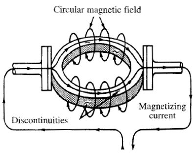
These poles attract fine magnetic particles and form an indication of the discontinuity. Figure shows the direct contact method for producing circular fields in a ring to indicate circumferential cracks.
To achieve a reliable test of the entire cylindrical surface, two magnetizations are required. This is done because the points of contact (where the current enters and leaves the ring) are not adequately magnetized for discontinuity indication. The ring must therefore be turned 90 degrees and then retested.
Direct contact method of 1 magnetizing ring shaped objects to locate
• circumferential discontinuities.

Circular Magnetization with Induced Current.
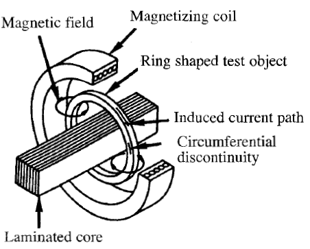
Figure shows a current flowing circumferentially around the ring, which can be induced by making the ring a single turn, short circuited secondary transformer. To accomplish this effect, a standard magnetizing coil can be used.
The ring is placed inside the coil with its axis parallel to that of the coil. When the coil is energized with alternating current, the arrangement constitutes an air core transformer; the magnetizing coil is the primary and the ring is the single turn secondary. The total current induced in the ring is greatly increased by inserting a laminated core of ferromagnetic material through the ring.

For materials with high magnetic retentivity, direct current can be applied in the technique called quick break, and the objects may then be tested by the residual method. Quick break is when a direct current field is caused to collapse suddenly because of an abruptly interrupted magnetizing current. The circular field generated by the induced current leaves the test object with a strong residual induction.
A bearing race is a good example of the type of object that can be tested advantageously by this method. For test objects made of soft material with low retentivity, the continuous method must be used and the collapsing direct current field method is not applicable. By using alternating current (or half wave direct current) in the magnetizing coil, the current may be left on and an alternating current ( or half wave direct current) of the same frequency as the magnetizing current is induced in the ring.
This current should be allowed to flow long enough to produce indications by the continuous method. Induced current method of magnetizing ring shaped objects to locate circumferential discontinuities.
Circular Magnetization of Hollow Test Objects.
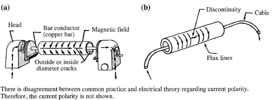
With hollow objects or tubes, the inside surfaces may be as important for testing as the outside surfaces. Since a magnetic field surrounds a current carrying conductor, it is possible to induce a satisfactory magnetic field by sliding the test object onto an internal conducting bar, as shown in Figure a. Passing current through the bar induces a circular magnetic field throughout the volume of the test object.
When a conducting bar is not available, an electrical cable may be passed through the test object and connected to receptacles in the magnetic particle unit, as shown in Figure b. For large diameter cylinders, the cable can be brought back on the outside of the test object, then threaded through again; each pass through increases the effective field by a factor of two. For long finished tubes, uninsulated conductors are not permitted because of arc bums.
Circular magnetization of cylindrical test objects using an internal current carrying conductor: (a) internal bar conductor; and (b) internal cable conductor.
