LONGITUDINAL MAGNETIZATION TYPES
Electrical current can be used to create a longitudinal magnetic
field in magnetic materials. When electric current is passed through
a coil, a magnetic field is established lengthwise or longitudinally
within the coil.
The nature and direction of this field are the result of the field
around the conductor which forms the turns of the coil. Application
of the right hand rule to the conductor at any point in the coil shows
that the field within the coil is longitudinal. Longitudinal
magnetization methods used are coil magnetization, field flow
magnetization and yoke magnetization.
WHAT IS COIL MAGNETIZATION
When magnetic material is placed within a coil, most of the
magnetic lines of force created by the electric current concentrate
themselves in the test object and induce longitudinal magnetization.
With a transverse discontinuity in the test object, magnetic poles are
formed on both sides of the crack by leakage fields. These poles
attract magnetic particles to form an indication of the discontinuity.
A magnetic field has been induced at right angles to the
discontinuity.
Test objects too large to fit in a fixed coil can be magnetized
longitudinally by making a coil from several turns of flexible cable.
The use of portable magnetizing equipment with cables and prods or
clamps broadens the use of magnetic particle testing. There is no
theoretical limit to the size of the object that can be tested in this
manner.
Important Considerations in Coil Magnetization
To induce an adequate longitudinal magnetic field with a coil, the
long dimension of the test object should be at least twice as great as
its short dimension, or end pieces should be added, and the long axis
of the test object should be parallel to the coil axis. This is especially
true in the case of irregularly shaped test objects, because the shape
of the object affects the direction of the induced flux.
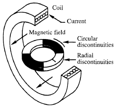
When a wheel, smaller in diameter than a coil, is placed in the
coil, as shown in Figure,
Coil magnetization of a
circular shape; radial discontinuities will be
indicated only in white areas (to reveal
radial discontinuities in the dark areas, the
test object must be rotated 90 degrees and
remagnetized); circular discontinuities will
be indicated in the shaded areas (to reveal
circular discontinuities in the white areas,
the test object must be rotated 90 degrees
and remagnetized).
a field is induced in the white areas of
the test object in such a direction that radial discontinuities create
indications. However, radial cracks in the shaded areas of the test
object are parallel (or nearly parallel) to the induced magnetic field,
so that few or no indications are formed. Furthermore, magnetic
poles and attractive forces occur in these areas. To indicate radial
discontinuities in the shaded areas, it is necessary to rotate the test
object 90 degrees and remagnetize it, although this technique is not
recommended.
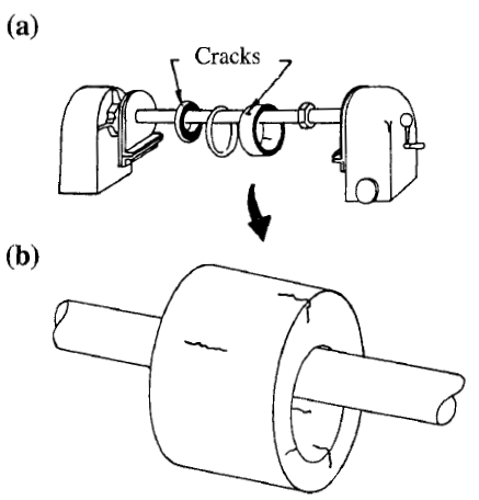
The detection of radial cracks in a test object of this shape is
more accurately and rapidly done using an internal conductor, as
shown in Figure. Better methods for finding circumferential
discontinuities in ring shaped test objects are shown in Figures. Ring shaped objects, discs or wheels are best checked for
circumferential cracks using the induced method of Figure. An
iron core, for example, is used with a coil surrounding it to produce
a toroidal field. This method has an advantage over the direct
contact method, shown in Figure, in that no danger of arcing or
burning exists, and the field is constant throughout the test object.
Internal conductor method
used to produce circular magnetization:
(a) several ring shaped test objects
magnetized simultaneously; and (b) close
up of a ring with cracks in several
locations and orientations.
FIELD FLOW MAGNETIZATION
Another means of producing a longitudinal field in a test object is
the field flow method. Here, the field is produced by electromagnets
and passed through the test object. The field is almost wholly
contained within the test object.
Whereas there is theoretically no limit to the length of a test
object that can be magnetized this way, as a practical matter with an
alternating current source, power requirements limit the effective
length to about 1.3 m (4 ft). However, special techniques using
direct current have accomplished longitudinal magnetization in one
step for lengths over 3 m (10 ft).
The field flow method has some advantages over the current flow
(coil) method in some production applications.
I. Moving a magnetizing coil several times may be impractical
and time consuming.
2. Test objects with length-to-diameter ratios less than 3: 1
require no special handling.
3. A consistent field wholly contained within a test object may
be required.
YOKE MAGNETIZATION
A longitudinal magnetic field can be induced in a test object or in
a limited area of a test object by using a handheld yoke. A yoke is a
U shaped piece of soft magnetic material, either solid or laminated,
around which is wound a coil carrying the magnetizing current, as
shown in Figure a.
When a test object is placed across the opening of the U shape
and the coil is energized, the test object completes the path of the
magnetic lines of force. This sets up a longitudinal field in the test
object between the ends of the yoke. Permanent magnetic yokes can
also be used to create a longitudinal magnetic field, as shown in
Figure b. Such yokes are often specified by their lifting power
or by the tangential field strength midway between the legs. The
tangential field strength is the field strength measured with a
magnetic penetrameter midway between the yoke legs.
Longitudinal lines of force induced by a yoke
magnet: (a) electrically energized yoke magnet; and
(b) permanent yoke magnet.


