This article is about technical specification and method statement related to commissioning and maintaining grounding systems.
The technical specification outlines the specific procedures and requirements for commissioning and maintaining grounding systems. It specifies the work practices and standards that must be followed.
The method statement defines the approach and methods that will be used to carry out the visual and mechanical inspections, electrical testing, and functional testing of grounding systems.
Electrical Commissioning / start-up checklist
Grounding Systems Nameplate Data
Date:___________
Facility:_______________ Equipment Location:______________ Project #: _____________
Equipment Designation:_______________________ Unit # _______ of _______ Units
Manufacturer:_________________ Serial number:_______________________
Model number:______________ Type:________ Shop Order number: _______________
Equipment Rating:___________ Volts:_________ Amps:_________ Amps S/C:___________
Technician:_____________ Sheet # ____ of ____
Visual and Mechanical Inspection
Here is a checklist or set of procedures for inspecting and ensuring the proper installation of electrical equipment and grounding system. These steps are crucial for safety, equipment integrity, and compliance with electrical standards. Here’s a breakdown of each instruction:
- Inspect for Physical Damage: Upon receiving the equipment, the first step is to visually inspect it for any physical damage that may have occurred during shipping. If any damage is found, it should be reported following the shipper’s instructions. This ensures that any shipping-related issues are addressed promptly.
- Compare Equipment Information: Verify that the equipment’s nameplate information matches the latest single-line diagram and equipment specifications. Consistency in this information is essential to ensure that the correct equipment is installed and configured.
- Check Bolted Connections: Use a calibrated torque wrench to check the tightness of accessible bolted connections. Proper torque is critical to maintain the integrity of electrical connections and prevent overheating or arcing. If the manufacturer’s instructions do not specify torque levels, refer to a predefined table in Electrical Equipment Commissioning.
- Inspect Ground System: Examine the ground system to ensure it is properly terminated at all devices and installed according to grounding specifications. Proper grounding is essential for electrical safety and to prevent voltage imbalances and electrical faults.
- Ensure Bonding of Ground Connections: Confirm that all regulated, isolation, control, and lighting transformer secondary ground connections are directly bonded to the facility’s grid ground network. This bonding ensures that the ground connections are effectively interconnected, which is crucial for safety and system performance.
These instructions demonstrate a systematic approach to ensuring the proper installation and safety of electrical equipment, emphasizing physical inspection, verification of information, torque checks, and adherence to grounding requirements. Following these steps helps prevent potential electrical hazards and ensures the reliable operation of electrical systems.
Operation and Electrical Testing of Grounding System
Here we outline various electrical testing procedures and measurements of grounding system that need to be performed as part of equipment commissioning and maintenance. Let’s break down each step:
- Fall of Potential Test per IEEE 81: This is a test to measure the ground resistance of the grounding system. It’s performed with a proper ground tester on a dry day. The results of this test are recorded. IEEE 81 provides standards for these tests.
- Resistance Measurement: Measure the resistance from the electrode to applicable locations. These measurements are important for verifying that the grounding system is effective and within acceptable limits. For maximum resistance values read this article Electrical Work in Plants and Refineries.
- Resistance of High Voltage System Ground Resistor: Measure the resistance of the high voltage system ground resistor. This resistor is a crucial component for safety and equipment protection. Record the measured resistance value.
- Insulation Resistance (Megger) Test: Perform an insulation resistance test on the high voltage system ground resistor to ground. This test is typically conducted using a Megger or insulation resistance tester. It checks the electrical insulation properties and safety of the resistor. Record the results of this test.
- Testing Nonsolidly Grounded System Protection/Alarm Devices: Test any protection and/or alarm devices associated with nonsolidly grounded systems according to the manufacturer’s instructions. This ensures that these devices are functioning correctly and will provide the necessary protection and alarms when needed.
- Testing Ground Fault Circuit Interrupters (GFCIs): Test all ground fault circuit interrupter receptacles and breakers to ensure proper wiring. This is typically done using a testing device specifically designed for GFCI testing. This step helps confirm that GFCIs will function correctly in the event of a ground fault.
These points emphasize the importance of electrical testing, grounding system integrity, and safety checks. Compliance with standards such as IEEE 81 and adherence to manufacturer’s instructions is crucial to ensure the safe and reliable operation of electrical systems and equipment. Recording the results of these tests is essential for documentation and compliance purposes.
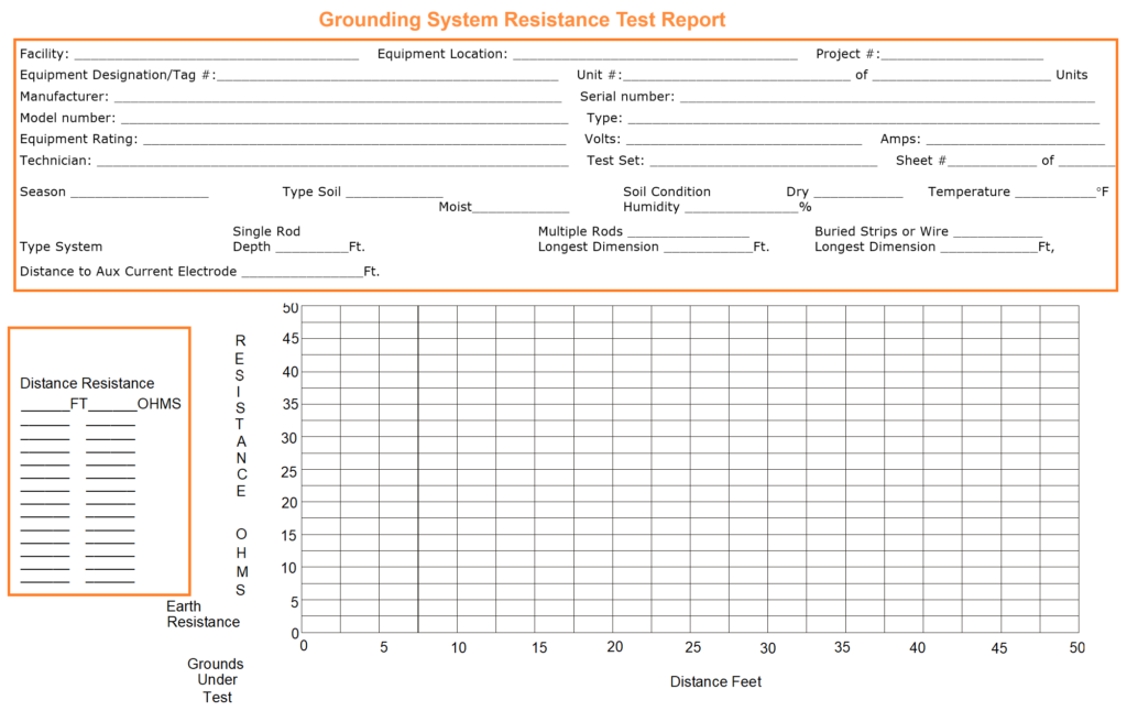
Grounding System Resistance Test Report
Related Articles and Sources of this Article:
- Electrical Equipment Commissioning
- Electrical Work in Plants and Refineries
- Electrical Safe Work Practices
- Electrical Safety Awareness and Aptitude Training
Institute of Electrical & Electronics Engineers Inc. (IEEE)
IEEE 81 – Guide for Measuring Earth Resistivity, Ground Impedance, and Earth Surface Potentials of a Grounding System.