This article is about COMPLETE OVERVIEW OF ADVANCE DCS SYSTEM and focusing to the engineers, technicians and supervisors. You will find lot of documents related to this article. Just navigate our website www.paktechpoint.com and find more articles. Please! Do not forget to subscribe our You tube channel also. Thanks in Advance.
COMPLETE OVERVIEW OF ADVANCE DCS SYSTEM
What Does DCS mean?
Distributed Control System (DCS). It is the department that deals with the electronics control boards which are processing & transmitting the control signals from the field to the operator& vice versa.
As we know that the signal which is coming from the transmitter needs to go through many boards to process it before it goes to the CP & to the operator & back to the field. These boards need maintenance & also need to be changed if they burned or defected. Sometimes we need to connect new distributed control loops to control new valves or pumps for example. Sometimes these boards needs only resetting or managing the software by using computer. All these work mention before is done by the DCS technician. This is the way of the work in the DCS department.
Type of DCS Hardware Unit
This section lists the most important DCS hardware equipments. It describes their functions, locations and specifications.
Most of the critical DCS equipments have two pairs, the primary and second is the backup. If the primary fails the backup will take over. This is referred to as Fault Tolerant (FT).
Most of the critical DCS equipments have two pairs, the primary and second is the backup. If the primary fails the backup will take over. This is referred to as Fault Tolerant (FT).
The following equipments are example of some of the units used in the company and are considered critical and any failure will cause a great impact on the process.
1. Unit Control Module (UCM).
2. Universal Field Multiplexer (UFM).
3. Field Input Output (FIO).
4. Universal Input Output (UIO).
5. Field Bus Module (FBM 100 SERIES).
Before explaining these units I would like to show some information
About some important cards and stations which are used in these units:
Control Processor (CP)
Description: The Control Processor or CP is one of the most important components of the system. It basically a small computer that runs programs to perform regular control, indication alarming and calculation for part of the operating unit. All CPs are Failure Tolerant
Carrier LAN Interface (CLAN)
Description: CLAN is the device that connects DCS nodes together. A node is a group of DCS components that is located in the same area and serves the same operating units. Within the node, DCS component are connected through redundant cables
called Node bus cables.
called Node bus cables.
Field bus:
Description: It is the cable that connects the CP with FBM, UCM, UIO, UFM and FIO. Similarly, the cable that connects the GW with its devices is called Field Bus.
Application Processor (AP)
Description:It’s a computer without monitor. Serves as storage media, also serves as a host for application like Flow Compensation, PI, Extract and Tag Search. One important function of the AP it monitors the health of DCS component for a particular area.
Application Workstation (AW)
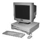
Description: Serves as the engineering workstation, used by system administration for development and maintenance. AW has got monitor, keyboard and mouse. It’s also used as a storage media and as a host to advance application like DMC
and Tank Inventory System (TIS), in addition to PI, Extract and Tag Search.
and Tank Inventory System (TIS), in addition to PI, Extract and Tag Search.
Workstation Processor (WP)
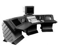
Description: Serves as the operator console to monitor the process units and perform controlling.
TYPE OF DCS UNITS: (in more details)
Unit Control Module (UCM)
Description: Serves as Input/Output for controllers (FIC, TIC, PIC, LIC). Input is from flow, temperature, pressure, level transmitter and output to valves.
1. Input card: to reads indication from the field and passes it to the CP as analog to digital converter (ADC).
2. Output card: to reads output from the CP and processes it & sends it to the field as digital to analog converter (DAC).
3. Communication card: It exists as integrated cabinet that contains communication cards called Spectrum Migration Interface (SMI CARD) to communicate with the CP and I/O cards.
4. Buffer card: it is the card which is store the data from the CP between the primary & secondary SMI card
Explanation of a single loop of UCM:
First the analog signal comes from the transmitter to the input card to converts the signal into digital signal which CP can accept it. Then it will go, through the SMI card to communicate with CP. The buffer card will store the data in between the SMI cards.
The SMI card will send the data to the CP & CP will take an action depending on the set point &it will send the signal back to the output card to back the signal again into analog signal to the valve. The CP connected to Carrier LAN to send all
the actions through Fiber optic to the WP station where the operator can check control the set point in the control room and Fiber optic To the WP station where the operator can check &control the set point in the control room.
Field Input Output (FIO) & Universal Field Multiplexer (UFM)
Description: FIO & UFM having same principle all serves as Input for indications (temp, mA, Volt & Contacts). It reads indication from the field and multiplexes it & passes it to the CP then to the control room. It exists as integrated cabinet that contains communication cards to communicate with the CP and I/O cards. Mainly utilized for temp and contacts.
Explanation of a single loop of UFM & FIO:
First the analog signal comes from the sensor to the inputs card (Temp card, mA card, volt card &contact).the signal of all cards will be converted into digital signal & it will multiplex. Then it will go through the SMI card to communicate with CP. The buffer card will store the data in between the SMI cards.
The SMI card will send the data to the CP. The CP connected to Carrier LAN to send all the actions through fiber optic to the WP station where the operator can check &control the set point in the control room.
Universal Input Output (UIO)
Description: Serves as Input for indications (temp, mA, Volt, contact) and as Output for digital contacts. It reads indication from the field and passes it to the CP. It also reads output from the CP and sends it to PLC, ESD or Interlocks. It exists as
integrated cabinet that contains communication cards to communicate with the CP and I/O cards.
integrated cabinet that contains communication cards to communicate with the CP and I/O cards.
Field Bus Module (FBM 100 series
The FBM serves as input & output of the controller. Input is from flow, temperature, pressure Transmitter and output to valves. It changes the signal from analog to digital & from Digital to analog as DAC & ADC.
We have many type of FBM module:
1. FBM 1: 8 channel analog input
2. FBM 2: thermocouple &mV input
3. FBM 4: 8 channel, 4 analog I &4 analog O.
4. FBM 5: 8 channel, 4 digital I &4 digital O.
5. FBM 6: 8 channel all input.
6. FBM 7: 16 contact input.
7. FBM 9: analog I/O, digital I/O.
8. FBM 41: 16 channel, 8analog I &8 analog O.
Explanations of a single loop of FBM 100 series:
First the analog signal comes from the transmitter to the input of the FBM to converts the signal into digital signal which CP can accept it. Then it will communicate with CP. The CP will take an action depending on the set Point &it will send the signal back to the output of the FBM to back the signal again into analog signal to the valve. The CP connected to Carrier LAN to send all the actions through fiber optic to the WP station where the operator can check &control the set point in the control room.
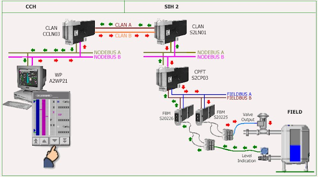
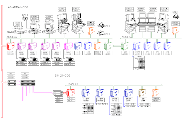
ARCHITECTURE LAYOUT OF SINGLE LOOPS OF FBM:
This figure below shows part of SAMREF DCS. It shows how A2 Area Node connects to SIH 2 Node.
Please read also: TRANSFER FUNCTIONS OF CONTROL SYSTEM
Deference to op , some superb selective information .