This article is about COMPLETE OVERVIEW OF PROGRAMMABLE LOGIC CONTROLLER PLC and focusing to the engineers, technicians and supervisors. You will find lot of documents related to this article. Just navigate our website www.paktechpoint.com and find more articles. Please! Do not forget to subscribe our You tube channel also. Thanks in Advance.
OVERVIEW OF PROGRAMMABLE LOGIC CONTROLLER PLC
A digital Electronic Device Uses a programmable memory to store instructions & to implement functions as
- Logic
- Sequencing
- Timing
- Counting
- Arithmetic
- In order to control machines & Process
- INPUT devices as switches & o/p devices as motors are connected to PLC.
- Controller monitors the inputs & o/ps according to the program stored in the PLC.
Uses Programmable Logic Controller
- Cost effective for controlling complex systems.
- Ladder logic programming can be applicable for other control system.
- Computational abilities allow more sophisticated control.
- Trouble shooting aids make programming easier and reduce downtime.
- Programming is easier and troubleshooting reduce downtime.
- Reliable components make these likely to operate for years before failure.
- Easy to modify a control system without rewiring the connections to input & o/p devices. Much faster than relay-operated systems
- Widely used for the implementation of logic control functions.
- Easy to use
- Reliability of PLC is greater
- Maintenance is easier
- PLCs take less floor space than do relay control panels.
- Can perform a greater variety of control functions than relay control
- Virtual real-time control becomes feasible
- Used for implementing automatic control of manufacturing systems
- Logical information is rapidly and repeatedly processed and immediately responded to with appropriate actions
- A series of logical decisions have to be made and a variety of actions taken on the basis of input that is obtained from appropriate sensors.
Features of PLC
- PLCs are designed to withstand with vibration, humidity, noise, temperature and any environmental changes.
- The main feature is interfacing for input and output is inside the controller.
- They are easily programmed.
Programmable Logic Control (PLC)
Definition – Dedicated computer for rapid processing of simple logic instructions in a defined time.
Purpose – Send and read signals that can be used to control and monitor devices.
Process – One of scanning all the devices (sensors, timers, etc.) in a cyclical time period.
PLC Control Approaches
Logic Control Method – This closed-loop method uses conditions and events to signal completion of a given step, and then triggers the execution of some other event. This is an asynchronous method of process control, because it does not always proceed in a constant time period.
Sequencing Method – This open-loop method uses timers to trigger the completion of one step and the beginning of the next. This is a synchronous control method.
Discrete Process Control
- Discrete process control systems deals with parameters and variables that change at discrete moments in time.
- Parameters and variables are also discrete in binary form.
- They can have either of two possible values, 1 or 0, values mean on/off, True/False, Object present or not present, high voltage value or low voltage value.
- The binary variables in DPC are associated with input signals to the controller & o/p signals from the controller.
- Input signals are generated by binary sensors, such as limits switches, Timer, Relay or photo-detector sensors that are interfaced to the process.
- O/p signals are generated by the controller to operate the process in response to the input signals & as a function of time.
- These o/p signals turn on or off switches, motors, valves, solenoid and other binary actuator related to the process.
- Discrete Process Control
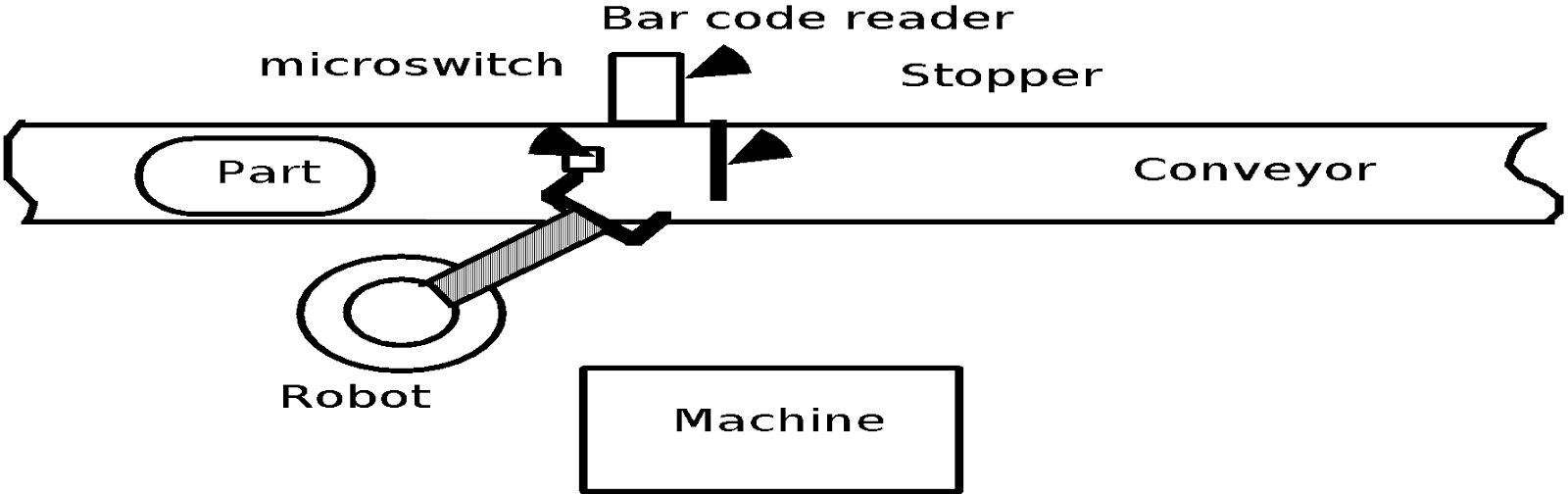
Three conditions and Solution
- The first condition can be indicated by means of a simple limit switch that sense the presence of the part at the conveyor, stop & transmits an On signal to the robot controller.
- The 2nd condition can be indicated by the forge press, which sends an On signal after it has completed the previous cycle.
- The 3rd condition might be determined by the photo-detector located so as to sense the presence or absence of the part in the forging die.
Uses of Discrete Process Control
- Widely used in discrete manufacturing as well as process industries.
- In discrete manufacturing it is used to control the operation of:
- Conveyors
- Automated Storage Systems
- Automated Transfer Lines
- Automated Assembly Systems
In process industries, discrete control is associated more with :
- Batch processing than with continuous processes
- Possible flow from one container to another during the cycle.
- Finally packaging

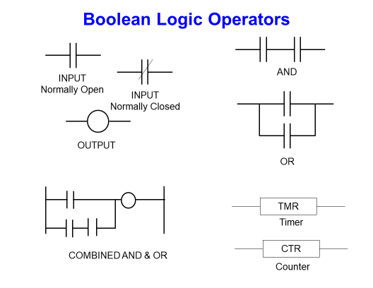
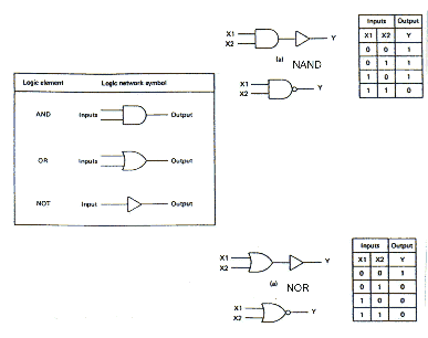
Logic Control Elements
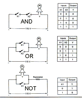
AND, OR , & NOT GATE
RELAYS
A switch that works on principle of an electromagnet is called a “relay” and give on off contact.
For a process control, it is desired to have the process start (by turning on a motor) five seconds after a part touched a limit switch. When the second limit approached, the process is finished automatically. We can stop or shutdown the system anytime by pressing emergency switch.


Example of a relay in a simple control

A Simple Relay Controller
COUNTER


TIMER


Counters and Timers
- Counters can be used in manufacturing to measure quantities such as production stock, inventory, and packaging
- Timers are used specifically to count clock pulses
- Timers and counters greatly expand the versatility of a PLC and allow the handling of some variable-type questions Virtually all PLCs on the market today include countering and timing capability
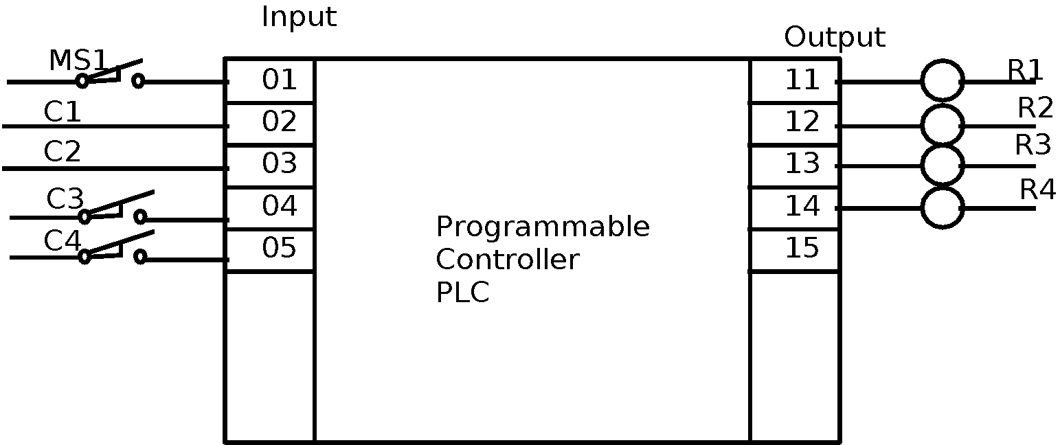
PLC ARCHITECTURE

PLC COMPONENTS
- Processor Microprocessor based, may allow arithmetic operations, logic operators, computer interface, local area network, functions, etc.
- Memory Measured in words.
EAPROM (Electronically Alterable Programmable Read Only Memory.
DC voltage I/P and O/P,
Low level analog I/P (INPUT),
High level analog (I/P)input and output(O/P),
Special purpose modules, e.g., high speed timers,
operator console
printer
simulator
EPROM loader
graphics processor
network communication interface
PLC SELECTION CRITERIA
- What I/O is required, i. e. the number of I/O, capability of expansion for future needs.
- What types of I/O are required, i. e. signal conditioning, on-board power supply for inputs, outputs, etc.
- What size of memory is required? This is linked to the number of I/O & a complexity of program used.
- What speed & power is required of CPU.
Logical Control
- Control actions are taken by making decisions depending on the values associated with various inputs or variables and the control logic in the program
- If a decision can be made by answering yes or no to a given question, it is referred to as a decision by attributes
- Is a part loaded in the machine?
- Is the tool path unobstructed?
- Is the AGV carrying a part?
- Decisions that cannot be made by answering yes or no are referred to as decisions by variables
- How long is the bar stock?
- What is the feed rate?
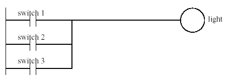
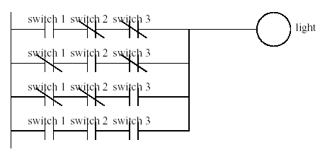
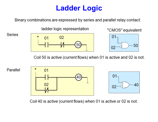
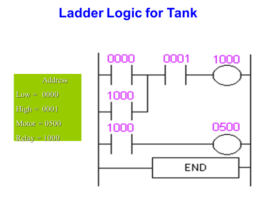
Ladder Logic Diagram
- Well established in industry in relation to the traditional electromechanical logic devices.
- Makes use of representations similar to electrical circuits in which a series connection represents
- a logical “and” and a parallel connection represents a logical “or”.
- Made up of inputs, outputs connected according to appropriate logic.
- Each rung in the ladder represents a set of logical relationships between the inputs that leads to a
- particular output.
- The output from one rung of the ladder could be used as an input in another rung of the same ladder.
- Except when special provisions are made, it is considered that all rungs in a given ladder logic diagram
- are executed simultaneously, so the order of the rungs on the ladder in general does not matter.

PLC WIRING DIAGRAM
CONTROL DEVICES
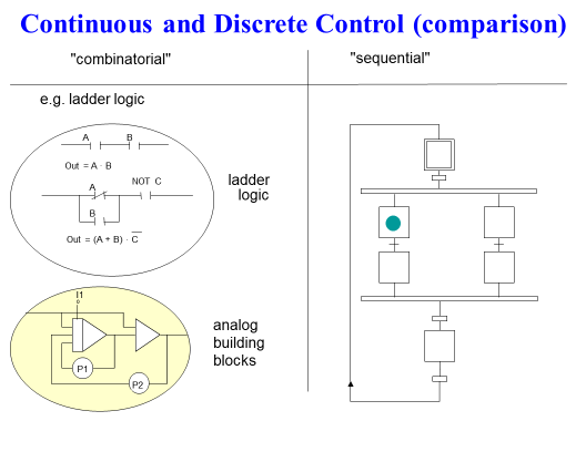
Continuous and Discrete Control (comparison)
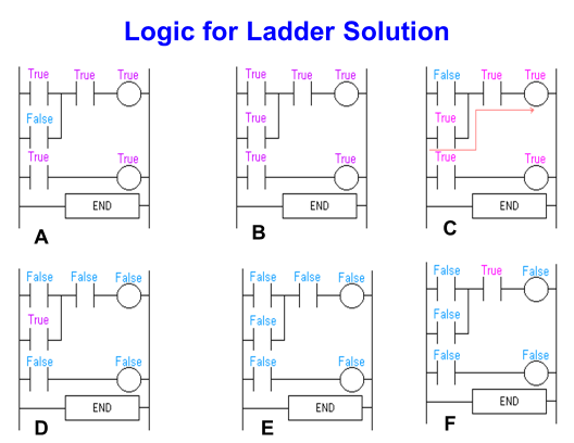
Ladder Logic

Ladder logic example
 |
| Add caption |
Solution:
IF sensor 2 is not tripped THEN energize solenoid 1 (Ingr A)
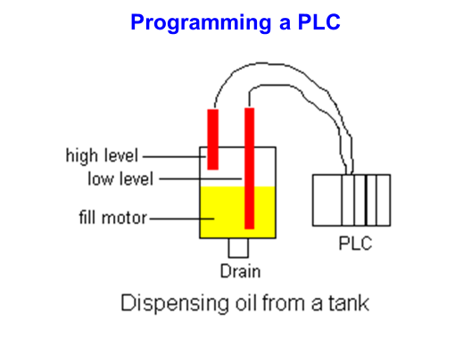

Q. PROGRAMMING EXAMPLE

SOLUTION:

Light Switch Examples Test

