- PURPOSE
1.1 This global engineering specification defines the minimum design requirements for the supply of control valve actuators and their accessories.
1.2 This specification is designed to detail standard requirements and, when specified, shall become an integral part of the unit specification.
- SCOPE
2.1 This specification applies to actuators and their accessories specified to be furnished with control valves.
2.2 Actuators covered by this specification are electronically or pneumatically controlled in modulating, on-off or low-cycle switch valve service and can be equipped with pneumatically or electrically operated actuators. The valve actuator may be equipped with a spring to force the valve to a fail-safe position.
2.3 All actuators supplied under this specification shall be designed for continuous operation in an ambient temperature range of -20° to +65°C (-4° to +150°F). Extreme ambient conditions will be identified on a project-by-project basis, and requirements will be defined on the unit specification.
2.4 Hydraulic actuators are not covered by this specification.
2.5 The additional requirements of high-cycle actuators (more than 40,000 on/off cycles per year)
are not covered by this specification.
2.6 Actuators and accessories shall conform to this engineering specification unless the accompanying unit specification indicates otherwise. In the event of conflict, the unit specification shall take precedence.
- RELATED DOCUMENTS
3.1 Air Products Engineering Documents
4AEL-620305 Electrical Work on Equipment Skids
3.2 International Society for Measurement and Control (Instrument Society of America) (ISA)
ANSI/ISA 7.0.01 Quality Standard for Instrument Air
- DEFINITIONS
4.1 Maximum shutoff pressure differential (MSPD) is the upstream safety relief valve setpoint or circuit design pressure against which a valve must open or close.
4.2 Unit specification refers to the document that is written to detail the requirements of a control valve for a specific set of process conditions. This document is transmitted by Air Products to the supplier for the purchase of the valve and is distributed to design disciplines for information purposes.
- DESIGN REQUIREMENTS
5.1 General Requirements
5.1.1 The control valve, actuator, positioner, and all accessories shall be supplied, piped, and mounted on the valve by the valve supplier. When equipment or accessories require mounting or tubing work to be done in the field, the supplier shall indicate this on the required supplier prints.
5.1.2 All valve accessories shall meet the electrical classification for the area in which the valve will be installed as defined on the unit specification. As a minimum, devices need to be weatherproof and watertight to NEMA 4X as defined by the National Electrical Manufacturer’s Association (NEMA) or IP 66 as defined by the European Committee for Standardization (CEN).
5.1.3 All fasteners used to secure actuation devices and their accessories shall be corrosion resistant and vibration resistant.
5.1.4 The actuator shall be supplied with a permanently attached stainless steel nameplate. The nameplate shall include, as a minimum, valve tag number, manufacturer’s name, model number, serial number, setpoints, American Society of Mechanical Engineers (ASME) pressure
rating class, and actuator maximum allowable working pressure. Individual accessories shall also
be tagged as defined on the unit specification. Wire tie-wrapped tags are not acceptable.
5.1.4.1 In addition to the engraved nameplate, rotary valves shall be match marked to assist correct reassembly alignment on site. This match marking shall record the alignment of both the valve shaft to actuator coupling and the actuator mounting to body. Match marking shall by applied by the manufacturer when the assembled valve has passed its seat leakage test and shall be
applied with the valve in the Air/Electrical failure position. Match marking of the shaft to actuator coupling shall be the Letter “C” when the valve is a Fail Closed valve and “O” when Fail Open. Whenever possible, match marks shall be hard stamped. Supplier shall also provide, by label or hard stamping, markings to show which way to rotate the valve shaft to its closed position.
5.1.5 All unused ports on the actuator or any supplied accessory must be plugged with a screwed metal plug. Plastic plugs are not acceptable. Weather-protected vent screens are required in all exhaust ports. Exhaust vents and electrical cable entries shall be positioned to prevent water from entering the ports per the orientation defined on the unit specification.
5.1.6 All instrument air connections on the actuator and supplied accessories shall be NPT threads unless defined otherwise on the unit specification.
5.1.7 Electrical cable and conduit entries for all accessories shall have the provisions to be supplied with a 1/2″ NPT conduit connection or M20 cable gland connection. Adapters shall be supplied if conversion is necessary. This requirement is further defined on the unit specification.
5.2 Failure Position
5.2.1 The failure position of a valve and actuator assembly is called out on the unit specification.
5.2.2 Failure position is defined as the position to which the valve moves when the activating power or signal (electrical or pneumatic) fails. The failure position will be achieved by a spring mounted in the actuator housing. Fail-last actuators must be specifically engineered per each application by taking into account all system components.
5.2.3 The failure modes of control valves are as listed below:
- Fail open (FO)
- Fail closed (FC)
- Fail last (FL): Special application requires engineering per application
5.2.4 Actuators may be specified with electrical accessories or components, which on electrical failure will cause the valve to travel to its failed position.
5.3 Actuator Sizing and Design
5.3.1 Actuators shall be sized to provide smooth regulation and hold open or hold closed against the maximum shutoff pressure differential (MSPD) and temperature conditions defined on the unit specification. Sizing shall be based on the minimum instrument air pressure as defined on the unit specification.
5.3.2 Actuator spring(s) shall be sized to move the valve to its failure position if loss of signal
(i.e., electrical or pneumatic) has occurred except when fail last is specified.
5.3.3 Actuator size shall be based on the manufacturer’s torque requirements for the valve size being considered at the MSPD across the valve.
5.3.4 The use of air reservoirs (volume tanks) to achieve failure positions must be approved by the
Air Products process controls engineer (see paragraph 6.6).
5.3.5 All pressure-containing components of the actuator shall be constructed of metal. Low- melting-point materials could fail catastrophically if exposed to impingement by flames and shall not be used unless prior written approval is obtained from the Air Products Technical Manager for Process Measurement and Control Hardware or designee.
5.3.6 The following actuator types are acceptable:
- Spring and diaphragm
- Piston
- Rotary piston lever
- Rotary diaphragm lever
- Rotary rack and pinion
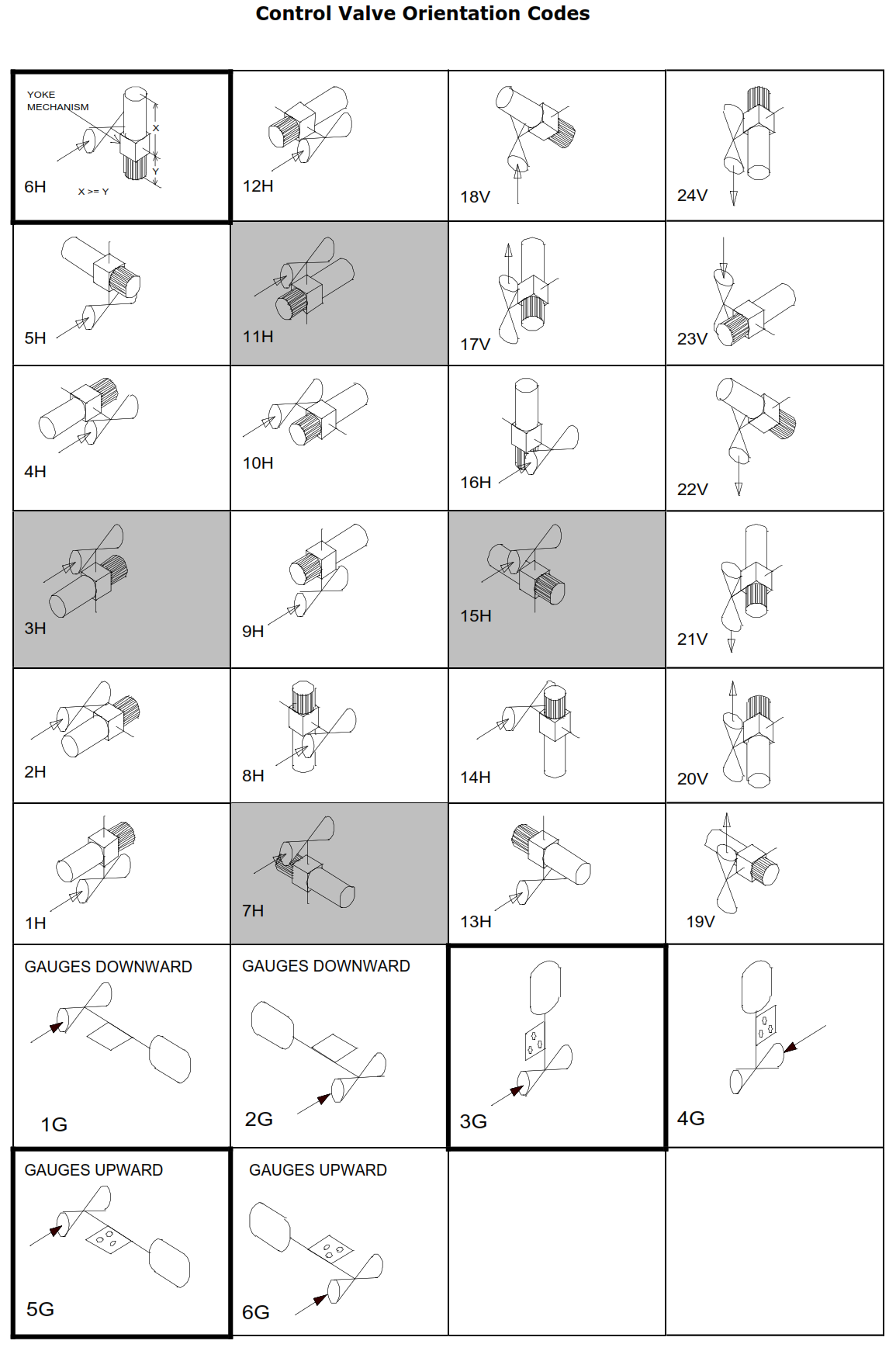
5.4 Actuator Orientations
5.4.1 Orientations shall comply with the following standard orientations shown in Figure 1 unless otherwise specified on the unit specification:
- Rotary Valves inside Cold Boxes (all types) – Orientation Code 6H
- Rotary Valves outside Cold Boxes – Orientation Code 6H
- Globe Valves inside Cold Boxes (all types) – Orientation Code 5G
- Globe Valves outside Cold Boxes (all types) – Orientation Code 3G
5.4.2 Control valve orientations, shown in shaded boxes in Figure 1, are orientations that are not permitted without obtaining prior written approval of the appropriate process controls PST Team technical leader.
Figure 1 Control Valve Orientation Codes
- ACTUATOR ACCESSORIES
6.1 Positioners
6.1.1 A direct-acting positioner shall be specified for all modulating control valves. Input signal types [0.2–1.0 bar g (3–15 psig) or 4–20 mAdc] will be specified on the unit specification.
6.1.2 Positioners shall be mounted on the valve actuator and tubed by the valve supplier.
6.1.3 Electro-pneumatic positioners shall meet the electrical classification specified on the unit specification.
6.1.4 Positioners shall be supplied with gauges for displaying input, output, and supply pressures.
Gauges shall be corrosion resistant and be in the units of measure defined on the unit specification.
6.1.5 Air filter regulators shall be supplied by the manufacturer and integrally mounted or tubed to the positioner (see paragraph 6.11).
6.1.6 Digital positioners, when required, shall use the HART protocol via the 4–20 mAdc analog output signal unless otherwise specified on the unit specification.
6.2 Limit Switches
6.2.1 Limit switch requirements will be defined on the unit specification.
6.2.2 The supplier shall mount and calibrate limit switches as defined on the unit specification.
6.3 Position Transmitters
6.3.1 Position transmitters, when required, shall be a 2-wire, loop-powered, 4–20 mAdc output device. Transmitter calibration shall be linear versus valve travel and shall be vibration resistant. The supplier shall mount and calibrate position transmitters per the unit specification.
6.3.2 Position transmitters shall meet the electrical classification as specified on the unit specification.
6.4 Volume Boosters/Quick Exhaust
6.4.1 The use of boosters and quick exhausts to speed up the operation of control valves shall be avoided if possible. Alternative methods shall be considered as follows:
- Increase air signal line size from 6 to 10 mm (1/4 to 3/8 in) OD or larger
- Increase solenoid valve size from 6 to 10 mm (1/4 to 3/8 in) or larger
- Enlarge actuator ports
6.4.2 Specific speed requirements will be defined on the unit specification. In several applications the speed requirement stated in the unit specification is not an absolute requirement and may be relaxed with the written approval of the Air Products specifier. If predicted speed is slightly over the specified time on the unit specification, the manufacturer shall inquire whether the speed requirement is critical before adding additional equipment to achieve the speed requirement.
6.4.3 If volume boosters and quick exhausts are required, the supplier shall integrally mount or tube these components to the valve actuator.
6.5 Solenoid Valves
6.5.1 The manufacturer and model number(s) for solenoid valves, when required, will be defined on the unit specification.
6.5.2 The solenoid valve shall be installed to vent the valve actuator, forcing the control valve to its failure position. “Energize to vent” or “de-energize to vent” will be further defined on the unit specification.
6.5.3 Solenoid valves shall be piped in the lines to the control valve actuator. It is not permitted to pipe the solenoid on the supply to the positioner or the signal to the positioner.
6.6 Air Reservoirs (Volume Tanks)
6.6.1 Air reservoirs may be used to achieve failure positions with cylinder-actuated valves or, in very special cases, will be defined on the unit specification to allow the valve to operate a number of cycles on instrument air failure.
6.6.2 The use of reservoirs shall be avoided if possible but, when essential, the manufacturer shall ensure that the relevant national pressure codes are applied.
6.6.3 When accessories are supplied loose for site mounting and connection, the supplier shall provide detailed dimension and connection drawings to assist in field installation.
6.7 Hand Wheels
6.7.1 When hand wheels are defined as required on the unit specification, they shall be supplied as a declutchable, manual-operator type.
6.8 Instrument Air Tubing
6.8.1 Valve tubing shall be seamless stainless steel or copper with a minimum diameter of
1/4 inch OD and fitted with Parker A-Lok tube fittings unless specifically defined otherwise on the unit specification.
6.8.2 All instrument air connection threads shall be NPT unless otherwise defined on the unit specification.
6.8.3 The supplier may supply larger-diameter pneumatic tubing, higher-capacity solenoid valves, and higher-capacity airsets to meet the required stroking time as defined on the unit specification.
6.9 Instrument Air Supply
6.9.1 Air quality shall be per ANSI/ISA 7.0.01 as a minimum requirement. Nitrogen with a dew point of -196°C (-320°F) might be used as “instrument air” in Air Products facilities. The supplier’s equipment shall operate successfully with either fluid as the Instrument Air source.
6.9.2 Air supply pressure is defined on the unit specification.
6.10 Instrument Air Filters
6.10.1 Instrument air filters shall be furnished when they are defined as required on the unit specification. Filters shall be provided with a metal bowl and drain. Plastic or glass bowls are not acceptable.
6.10.2 The normal mesh size of the filter shall be 25 micron maximum unless either components supplied by the manufacturer or the unit specification requires more stringent filtration.
6.10.3 Filters shall be integrally mounted or tubed to actuator components. When specified, instrument air filters shall be mounted and piped with drains pointing down to suit valve orientation (see paragraph 5.4).
6.10.4 Filters shall be provided with an inlet supply gauge. The filter shall be rated for either a minimum of 10.3 bar g (150 psig) or a higher rating if defined on the unit specification.
6.11 Air Sets (Filter Regulators)
6.11.1 Filters regulators shall be furnished when they are defined on the unit specification. Air filter regulators shall be provided with a metal bowl and drain. Plastic or glass bowls are not acceptable.
6.11.2 The normal mesh size of the filter in the air set shall be 25 micron maximum unless either components supplied by the manufacturer or the unit specification requires more stringent filtration.
6.11.3 Filter regulators shall be integrally mounted or tubed to actuator components. Filter regulators, when specified, shall be mounted and piped with drains pointing down to suit valve orientation (see paragraph 5.4).
6.11.4 Air sets shall be supplied with outlet pressure gauges except when a positioner is furnished with a supply gauge as part of the actuation package. The filter regulator shall be rated for either a minimum of 10.3 bar g (150 psig) or a higher rating if defined on the unit specification.
- ELECTRICAL WIRING REQUIREMENTS
7.1 The electrical requirements listed in Section 7 apply to integrated valve actuator assemblies. For integrated valve actuator assemblies (where all of the accessories are pre-wired to a single interface point), installation and wiring shall meet the requirements of all standards and area classification listed on the unit specification, and shall comply with all local codes and regulations for the Country of Final Destination.
7.2 If the final destination of the Control Valve is United States, the following shall apply:
7.2.1 Wiring associated with the integration of actuator assemblies in skidded assemblies shall be as listed in engineering specification 4AEL-620305.
7.2.2 Flexible Conduit
7.2.2.1 The use of flexible conduit for interconnection of wiring for consolidation of wiring terminations into a single enclosure or housing is permitted. The bend radius of flexible conduit shall not be less than the manufacturer’s recommended minimum, as to minimize stress on components and fittings.
7.2.2.2 Splicing of wiring is not permitted inside conduit. Housings or fittings approved for wiring connections must be used if provided wiring is not of sufficient length. Terminal assemblies, insulated quick-disconnect-type connectors, and insulted butt-splices can be used at connection points. Wire nuts shall not be used.
7.2.2.3 Any housings or conduit bodies shall be supported by mounting brackets or by means of rigid coupling to an existing rigidly mounted housing. Composite housings, like molded solenoid valve coils, shall not be used for support.
7.2.3 Hazardous Locations (Class I, Division 2)
7.2.3.1 Liquidtight conduit shall be limited to Type LA liquidtight metal flexible conduit (LFMC). Conduit fittings shall be approved for use in hazardous locations per Article 501 of the National Electric Code.