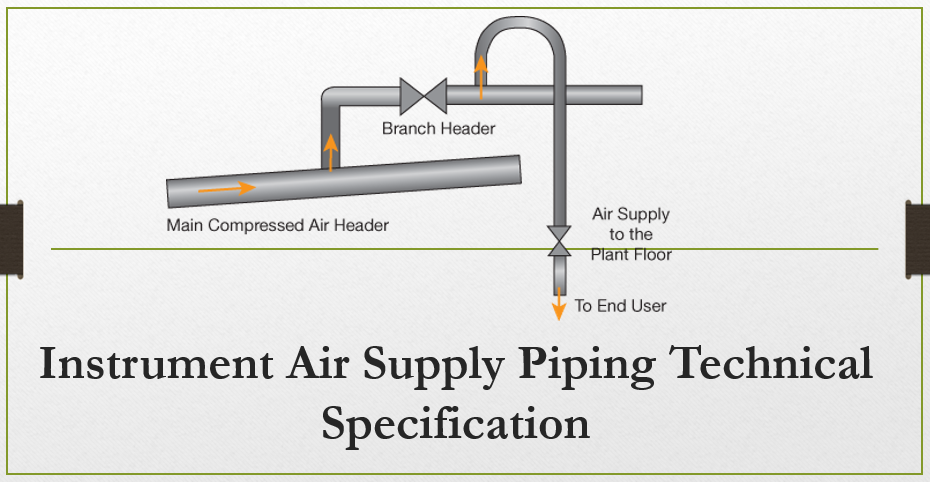
1. Purpose – This article is about Instrument Air Supply Piping Technical Specification and this fabrication and erection technical specification specifies for instrument contractors acceptable materials of construction for instrument air supply systems with design pressures no greater than 10.3 bar g (150 psig).
2. Instrument Air Supply Piping Technical Specification
- This specification applies to the materials of construction for all dry instrument air, nitrogen, or with nitrogen as the back-up fluid supply systems. This specification does not apply when any other fluid such as oxygen or a combustible is used.
- This specification is not complete for the stainless steel Victaulic Pressfit system option unless read along with Appendix A installation instructions.
3. RELATED ARTICLES, CODES AND STANDARDS
Installation of Field Instrumentation
Fabrication and Erection of Process Piping
3.2 American Society of Mechanical Engineers (ASME)
B16.11 Forged Fittings, Socket–Welding and Threaded
3.3 American Society for Testing and Materials (ASTM)
A 105/A 105M Specification for Carbon Steel Forgings for Piping Applications
A 106 Specification for Seamless Carbon Steel Pipe for High-Temperature Service
A 269 Specification for Seamless and Welded Austenitic Stainless Steel Tubing for General Service
4. GENERAL
- The instrument contractor’s responsibility will be from the root valve on the primary instrument air system, which will be installed by the mechanical/piping contractor.
- Refer to Installation of Field Instrumentation, Section (PRESSURE TESTING).
5. ACCEPTABLE MATERIALS
5.1 Any one of the following three piping systems is considered to be acceptable for this service.
5.1.1 Carbon steel socket welded system
- Pipe shall be nominally sized 1/2″–1″, standard weight, seamless carbon steel pipe with plain ends. Material shall be ASTM A 106, Grade B.
- Threaded pipe shall be used to mate to threaded valves and shall be minimum of Schedule 80.
- Socket weld fittings shall be Class 3000, ASTM A 105 according to ASME B16.11.
- Refer to 4WCE-670200 for all socket welded systems.
5.1.2 Carbon Steel threaded system
- Pipe shall be nominally sized 1/2″–1″, Schedule 80, seamless with plain ends. Material shall be ASTM A 106, Grade B.
- Threaded fittings shall be Class 2000, ASTM A 105 and in accordance with ASME B16.11.
- Pipe thread sealant shall be used in making up joints. Use one of the following types of thread sealant from one of the listed manufacturers:
- PTFE thread tape
- Federal Process Co. (Thred Tape)
- Permacel Div. (Ribbon Dope #412)
- 3M Co. (Scotch 48)
- Paste-type PLS-2 pipe thread and gasket sealer from Federal Process Company
- PTFE thread tape
- Threaded pipe shall not be used in any system that might contain moisture.
5.1.3 Stainless steel Victaulic Pressfit system
Note: The use of the Pressfit system in high-reliability systems shall be thoroughly evaluated before being approved because of the large number of mechanical joints and the thin-wall construction.
- Pipe shall be nominally sized 1/2″–1″, Schedule 5S 0.065″ wall thickness stainless steel, electrical resistance welded (ERW). Material shall be ASTM A 269 Grade 304/304L and shall be provided by only the Victaulic Corporation. No other supplier of pipe shall be used.
- Fittings shall be electrical resistance welded (ERW), stainless steel with Pressfit ends according to ASTM A 269, Grade 304/304L and shall be according to the following Victaulic part numbers:
- Transition nipple Victaulic Part #587
- Reducing tees (pressfit/pressfit/female thread) Victaulic Part #588
- 90-degree elbow Victaulic Part #590
- 45-degree elbow Victaulic Part #591
- Concentric reducers Victaulic Part #594
- Flange adapters Victaulic Part #595
- Adapters Victaulic Part #596
- Full-size tees Victaulic Part #592
- Reducing tees (pressfit/pressfit/pressfit) Victaulic Part #593
- Couplings Victaulic Part #597
- Couplings Victaulic Part #598**
- Female adapters Victaulic Part #599
** Note: Part #598 couplings may be used only if part #597 couplings are not feasible as a result of piping constraints.
- All Pressfit fittings shall be supplied with Grade “E” (EPDM) O-rings installed.
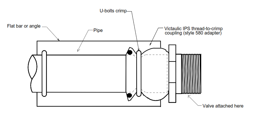
- Installation of this system shall be in strict compliance with the Victaulic Pressfit installation manual. A link to the installation manual can be found in Appendix A. Figure 1 depicts the recommended support arrangement for end-of-the-line fittings (threaded connection to valves).
- A portable Pressfit TM PFT-500 tool with 1/2″ and 1″ jaws is available from Victaulic for rental or sales. Contact Victaulic at (610) 559-3300 for tool prices and, if need be, a more recent installation manual than is shown in Appendix A.
Note: Before the Pressfit operation is accomplished, all pipe shall be prefitted and marked with indelible ink to ensure the end is fully inserted into the fitting.
Figure 1 Victaulic Stainless Steel Pressfit System
Recommended Support Arrangement for
End-of-the-Line Fittings (Threaded Connections to Valves)
Plan View
Notes:
1) Adapter is secured to pipe by U-bolts and flat bar or angle.
2) Different arrangements call for a different detail, consult the Air Products representative (who will consult with their Mechanical Systems engineer).
Victaulic Pressfit Installation Manual
Note: You must have Adobe Acrobat Reader V3.01 or later to open the Victaulic Pressfit installation instructions behind Pressfit.pdf link. To check whether this is the most recent copy, visit www.victaulic.com.
Victaulic Pressfit

