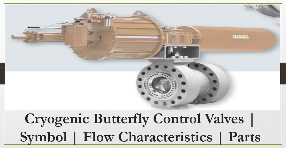
This article is about design requirements for the fabrication and installation of Cryogenic Butterfly Control Valves as per international standards and codes, Butterfly Control Valves Symbol, Butterfly Control Valves Flow Characteristics and Parts of Butterfly Control Valves.
First check to basic video of working principle of Butterfly Control Valves.
1. Purpose of this article – This engineering technical specification defines design requirements for the fabrication and installation of cryogenic extension butterfly control valves in gas and liquid cryogenic service [i.e., below -30°C (-20°F)] and installed internal or external to cold boxes.
2. Cryogenic Butterfly Control Valves | Symbol | Flow Characteristics
- This engineering specification applies to all cryogenic extension -service butterfly control valves, which will be installed internal and external to cold boxes. Exception: This specification does not apply to ultrahigh-purity plants or vacuum jacketed-design cold boxes.
- Butterfly valves described herein are intended for use in liquid and gaseous air, argon, nitrogen, hydrogen, methane, carbon monoxide, and oxygen fluid services typically encountered in cryogenic, gas-processing plants. Refer to the unit specification for individual orientations and process conditions.
- Actuation and requirements of accessories for a cryogenic butterfly valve are addressed in specification 4WPS-VALV03 and the unit specification.
- Cryogenic extension butterfly valves shall conform to this engineering specification unless the accompanying unit specification indicates otherwise. In the event of conflict, the unit specification shall take precedence.
3. Related Article and Codes
Process Clean (Class B) Inspection and Acceptance Requirements
Oxygen Clean (Class AA) Inspection and Acceptance Requirements
Control Valve Actuators and Accessories
Fluid Controls Institute (FCI)
FCI 70-2 Control Valve Seat Leakage
American Petroleum Institute (API)
STD 598 Valve Inspection and Testing
American Society of Mechanical Engineers (ASME)
ASME BPVC, Section VIII, Div. 1 Pressure Vessels.
ASME B16.34 Valves – Flanged, Threaded, and Welding End.
ASME B16.5 Pipe Flanges And Flanged Fittings.
ASME B31.3 Process Piping.
European Committee for Standardization (CEN)
EN 10204 Metallic products—Types of inspection documents
4. DEFINITIONS
What are Cryogenic Extension Butterfly Valves? Refer to rotary valves butterfly valves designed for cryogenic duty with a single flange connection at the top end of the extension tube. These valves trims are not required to be fully extractable. Maintenance access to the valve’s internals is by removing the valve from the piping system.
What are High-performance butterfly valve? Refers to a butterfly valve that can be characterized by having a heavy shaft and disc as well as a fully rated body with seat design that shuts off against high pressures. The shaft and disc are mounted to allow the disc to swing clear of the seat area to minimize wear and torque. The offset-disc design allows the seat to be replaced without removing either the shaft or disc. The valve has control capabilities beyond 60 degrees rotation.
5. BUTTERFLY CONTROL VALVE DESIGN REQUIREMENTS
5.1 Valve Body
- The valve shall be a high performance butterfly valve designed for cryogenic temperatures defined as -198° to +65°C (-325° to +150°F). Specific process conditions will be detailed on the unit specification.
- Stainless steel is the recommended body material for cryogenic service. Aluminum and bronze body materials may not be considered without prior, written, Air Products approval of the manufacturer’s design. This will be considered when the supplier proves it has economic advantages over a similar stainless steel offering. The pressure-temperature rating of all pressure-containing parts of the valve shall comply with ASME B16.34 corresponding to ratings for Classes 150, 300, and 600.
- All pressure-containing parts of the valve made wholly or partly from segments of castings, forgings, bars, plates, or tubular products welded together as a complete assembly, shall comply with ASME B16.34. Weld fabrication and heat treatment of welds shall be in accordance with the ASME BPVC, Section VIII, Division 1. Nondestructive examination of welds shall be performed in accordance with the ASME BPVC, Section VIII, Division 1, as required per the code to warrant joint efficiency. All pressure-containing parts shall be tested to API STD 598.
- The valve body for this application shall be classified as a fully rated body. A derated valve body may be used only after obtaining prior, written approval from Air Products.
- Body end connections shall be wafer-style unless otherwise defined on the unit specification. Wafer-style valve bodies shall be designed to be placed between raised-face mating flanges per ASME B16.5 Classes 150, 300 and 600 as defined on the unit specification. Buttweld-end butterfly valves are currently being considered for future application in cryogenic service. This specification does not currently include the requirements for buttweld cryogenic butterfly valves.
- No gasketed nor bolted joints are allowed on valve-body components that are located inside the cold box or insulated area. This includes removable plates over the lower-bearing cavity. For wafer-style valves this requirement is preferred but not an absolute requirement with exceptions being kept to a minimum.
- All materials considered as pressure-containing parts are subject to proof of material certification to CEN EN 10204, Type 3.1.B. The supplier shall retain copies of these documents for a ten-year time period for possible review by Air Products.
- A valve referenced for purchase under this specification will be a component of a process piping system that will be designed and installed in accordance with ASME B31.3 unless other local codes and standards take precedence.
5.2 Extension Tube
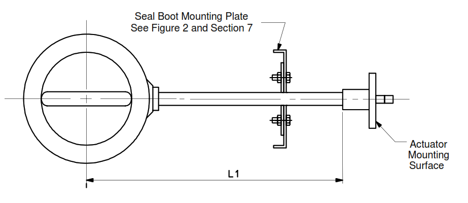
- The valve shall be furnished with an extension tube, extended to a dimension as specified in the unit specification (see Figures 1 and 4). The extension tube shall be an integrally welded or cast component of the valve body. Flange-type construction of the connection between the extension and valve body shall not be provided without obtaining prior, written approval from Air Products.
- 5.2.2 The extension material shall be Tp 304 or 316 grade, thin-wall, stainless steel to minimize heat leak. The extension wall thickness shall be governed by the ASME valve-body rating as specified on the unit specification.
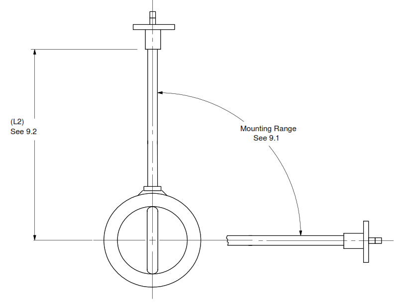
- 5.2.3 The unit specification will detail the requirement for a seal boot or plain extension. When a seal-boot extension is specified, details shown in Figures 1, 2, and 3 of this specification shall apply. A plain extension does not require a mounting plate, and details for installation can be found in Figure 4.
- 5.2.4 Plain and seal-boot extensions shall be furnished to the “standard extension length” referencing dimensions “L1” and “L2” shown in Table 1. Exceptions to the standard extension lengths shown in Table 1 will be shown on the unit specification when required. The “standard extension lengths” differ on plain and seal-booted extensions.
5.3 Seat Leakage
- 5.3.1 Permitted seat leakage for a cryogenic, butterfly control valve shall be in accordance with ANSI/FCI 70-2, which defines the levels of leakage from Class I to Class VI.
- 5.3.2 The leakage rate specified on the unit specification is stated as the minimum requirement. Class VI shall be furnished unless a lower level is stated as an absolute requirement on the unit specification.
5.4 Bolting
The packing nuts and bolts along with the actuator mounting nuts and bolts shall be stainless steel. Mounting-plate bolts shall also be stainless steel.
5.5 Packing and Gaskets
- 5.5.1 All valve packing, gaskets, and O-rings shall be designed to operate at the ASME pressure rating for the valve and at a flowing process temperature range of -198° to +65°C (-325° to +150°F) unless stated otherwise in the unit specification.
- 5.5.2 The standard stem packing for cryogenic, butterfly control valve service is PTFE. Double PTFE v-ring or braided PTFE packing designs are acceptable. The required packing type will be designated on the unit specification.
- 5.5.3 Two additional designs of stem packing exist for use in a cryogenic, butterfly control valve. One design is the standard Grafoil packing, consisting of a series of laminated Grafoil rings. The second design is a live-loaded Grafoil packing that is self-adjusting and made up of laminated Grafoil rings with a set of spring washers to provide uniform packing pressure. Standard Grafoil packing is preferred in hydrocarbon and toxic service. Live-loaded packing is recommended for use in high-cycle or fugitive-emission service.
- 5.5.4 Asbestos gaskets and packing are not acceptable.
- 5.5.5 The bonnet area shall be designed to accept a 6 mm (1/4 in) FNPT packing purge connection in the area between the two packing sets when required. If required, this purge connection will be called out in a note on the unit specification as “Double Lantern Ring Packing.” A 3 mm (1/8 in) connection is acceptable when allowed by ASME B16.34 for smaller valve sizes.
5.6 Bearings
5.6.1 The upper and lower shaft bearings and the thrust bearing (if required) shall be of the manufacturer’s standard design for this application. Material shall be compatible with the process conditions stated in the unit specification.
5.7 Valve Identification
- 5.7.1 Each valve shall be furnished with a serial number or other traceable identification marking, which shall be engraved on a stainless steel nameplate. This nameplate shall also include the valve tag number from the unit specification. This nameplate shall be permanently attached to the valve actuator.
- 5.7.2 A direction-of-flow arrow shall be permanently attached to the valve body and the actuator mounting flange. The valve tag number shall be engraved on a stainless steel tag and permanently attached to the actuator mounting flange.
- 5.7.3 All tags and nameplates shall be stainless steel. Wire, tie-wrapped tags are not acceptable. Any additional tagging requirements will be specified either as part of the unit specification or the purchase order document.
5.8 Actuation and Accessories
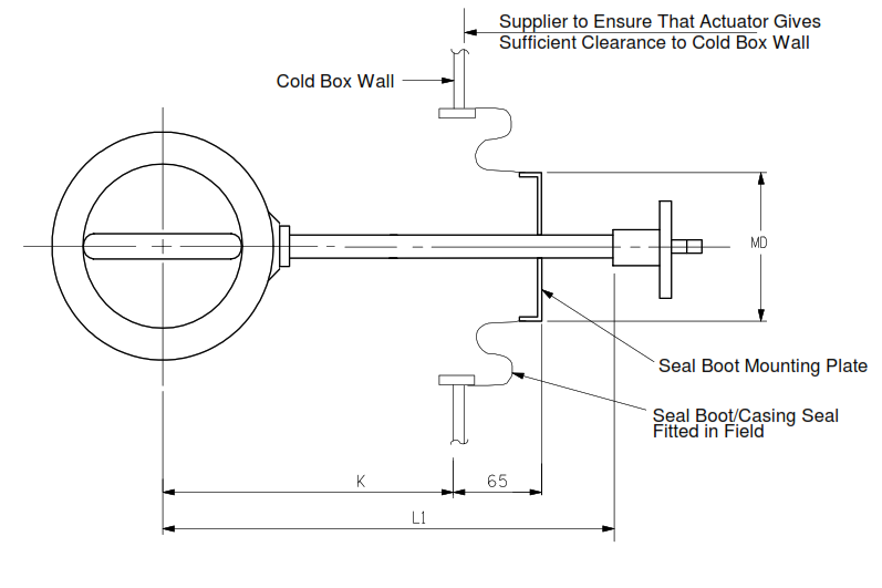
- 5.8.1 The supplier shall ensure that the actuator and all accessories dimensionally clear the cold box wall with appropriate maintenance removal clearances maintained (see Figure 3).
- 5.8.2 When required, supplier dimensional drawings shall show the reference dimension of the cold box wall to actuator clearance.
6. CLEANING
Cleaning of all process wetted parts to meet the requirements of 4WPI-SW70002 or 4WPI-SW70003 will be defined on the unit specification.
7. SEAL-BOOT MOUNTING PLATE
- Seal-booted valve extensions are designed to be mounted in insulated cold boxes. The function of the seal boot is to contain the purge gas and insulation material of the cold box. The seal-boot extension is also designed to provide piping system flexibility.
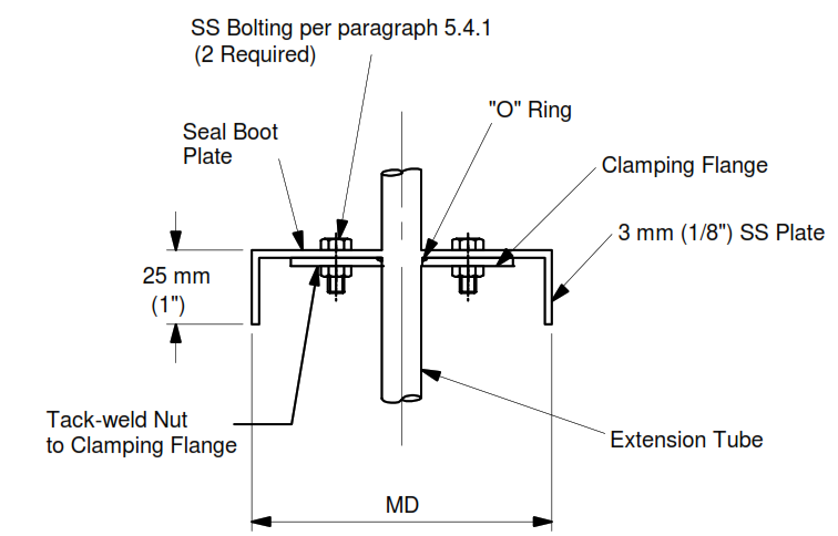
- The seal-boot mounting plate shall be 3 mm (1/8 in), Tp 304 or 316 SS plate. Dimensions and details are shown in Figures 1 and 2 and in Table 1.
- The seal-boot mounting plate is designed to support the seal-boot casing seal as shown in Figure 3. The seal-boot plate is tightly bound against the extension tube by compressing an O- ring between the clamping flange and the seal boot plate as shown in Figure 2.
- The supplier shall furnish the seal-boot mounting plate fitted loosely on the valve extension for final placement by the Air Products cold box fabricator as shown in Figure 3.
Figure 1 – Cryogenic Extension Butterfly Valve with Seal Boot Plate
Figure 2 – Seal Boot Mounting Plate Detail
Table 1
Cryogenic Butterfly Valve Dimension Table
| Nominal Valve Size | (L1) Standard Cold Box Extension (See Figs. 1&3) | (L2) Standard Field Extension (See Fig. 4) | (MD) NPS Pipe Dia. Seal Boot Plate Dia. (See Fig. 2) |
(K) Buried Depth (See Fig. 3) |
|
| DN | NPS | ||||
| 80 | 3 | 610 (24) | 355 (14) | 219 (8 5/8) | 400 (15 3/4) |
| 100 | 4 | 610 (24) | 406 (16) | 219 (8 5/8) | 400 (15 3/4) |
| 150 | 6 | 711 (28) | 457 (18) | 219 (8 5/8) | 500 (19 11/16) |
| 200 | 8 | 813 (32) | 508 (20) | 273 (10 3/4) | 625 (24 5/8) |
| 250 | 10 | 813 (32) | 610 (24) | 273 (10 3/4) | 625 (24 5/8) |
| 300 | 12 | 914 (36) | 711 (28) | 273 (10 3/4) | 715 (28 1/8) |
| 350 | 14 | 965 (38) | 762 (30) | 273 (10 3/4) | 765 (30 1/8) |
| 400 | 16 | 965 (38) | 890 (34) | 273 (10 3/4) | 765 (30 1/8) |
| 450 | 18 | 965 (38) | 914 (36) | 273 (10 3/4) | 765 (30 1/8) |
| 500 | 20 | 965 (38) | 965 (38) | 273 (10 3/4) | 765 (30 1/8) |
| 600 | 24 | 1118 (44) | 1118 (44) | 273 (10 3/4) | 920 (36 1/4) |
| 750 | 30 | 1219 (48) | 1220 (48) | 273 (10 3/4) | 1020 (40 3/16) |
| 900 | 36 | 1422 (56) | 1422 (56) | 273 (10 3/4) | 1220 (48 1/16) |
| 1050 | 42 | 1524 (60) | 1524 (60) | 273 (10 3/4) | 1335 (52 9/16) |
| 1200 | 48 | 1626 (64) | 1625 (64) | 273 (10 3/4) | 1435 (56 1/2) |
8. SEAL-BOOT MOUNTING PLATE INSTALLATION
- Cryogenic butterfly valves with seal-boot mounting plates are designed to be mounted with the extension tube in the horizontal position as shown in Figure 3. The seal boot area shown in Figure 3 is designed to hold the cold box purge and insulation medium while providing flexibility for the piping system.
- The seal boot (casing seal) and seal-boot mounting plate are positioned on the extension tube in the field after the cold box has been erected in the field.
- Dimension “K” in Figure 3 is shown for reference only and might vary on actual installation drawings.
Figure 3 – Installation Detail (Cold Box) Seal Boot, Cryogenic Butterfly Valve, Gas and Liquid Service
9. PLAIN EXTENSION INSTALLATION
- For non-cold-box (field) installation (see Figure 4), the preferred orientation is with the valve shaft vertical. If this is not practical, the extension may be orientated in any position that keeps the packing area at any angle at or above the horizontal. No mounting plate is required for this installation, and the unit specification will indicate a “plain” extension.
- The extension-length dimension “L2” for field-installed valves is less than the “L1” dimension for cold box valves (see Table 1). Shorter standard extensions are used in field installations since buried depth requirements do not need to be considered.
Figure 4
Installation Detail (Field) Plain Extension, Cryogenic Butterfly Valve, Gas and Liquid Service
Following are application of Triple-eccentric Butterfly Valves.
– Refineries – LNG, cryogenics – Petrochemicals – Steel works – Solar – Compressors – Ammonia, urea – Chemicals – Power plants – Steam and gas turbines
