This article is about DDC BASED HVAC CONTROL PANEL SEQUENCE OF OPERATION for Substation Building.
DDC BASED HVAC CONTROL PANEL SEQUENCE OF OPERATION (Substation Building)
- System description
- Description of DDC panel.
- Description of the HVAC equipment.
- Application of field devices.
- Normal operation
- Start-up & Shut down.
- Conditions for changeover to standby unit.
- Temperature control.
- HM/Operator unit.
- Alarms and indications.
- Emergency operation.
- Emergency Shutdown.
- Fire Alarm.
- Gas Alarm (H2S/Combustible Gas).
")
1. System Description:
Description of DDC based control panel:
The intent is to assure that the control system automatically controls the HVAC system, by maintaining the desired conditions, while minimizing energy use and use of services of operator. To achieve this, the control system utilizes a direct digital controller (DDC), MI machine interface) touchscreen type, and electric/electronic field devices such as, (operator temperature sensors, differential pressure switches, motorized dampers in outside, supply & return air ducts etc.
The control system is housed in an enclosure made up of a single compartment. The enclosure is a powder coated galvanized steel box with an IP42 rating and is intended for floor mounting in non-hazardous location inside the building. The enclosure houses a dedicated Siemens brand controller and other control components like control transformer, miniature circuit breakers, fuses, pushbuttons, indication lights, control relays, audible alarm and other accessories. The control panel is also provided with ventilation fan.
The panel is fed with only one normal power supply, one from regular supply and the other from emergency supply. In event of fault in regular supply the source will be automatically -changed within the panel to emergency supply. The power supply to the panel is 230V/Ph/60Hz. This voltage is stepped down to 24V AC/Ph/60Hz to power-up the control circuit and the field devices.
The control system controls & monitors parameters that include but not limited to, all these functions are provided on the operator interface module.
a. Start/stop of supply fans of AHUS, EFs, CFU’s and BF’s.
b. Monitoring of ‘Run’ & ‘Trip’ status of supply fans of AHUS, ACCU’s, EFs, CFUs, BF’s and EDH.
c. Monitoring of No Airflow / Broken Belt status of supply fans of AHUS, EFs, CFUs and BF’s.
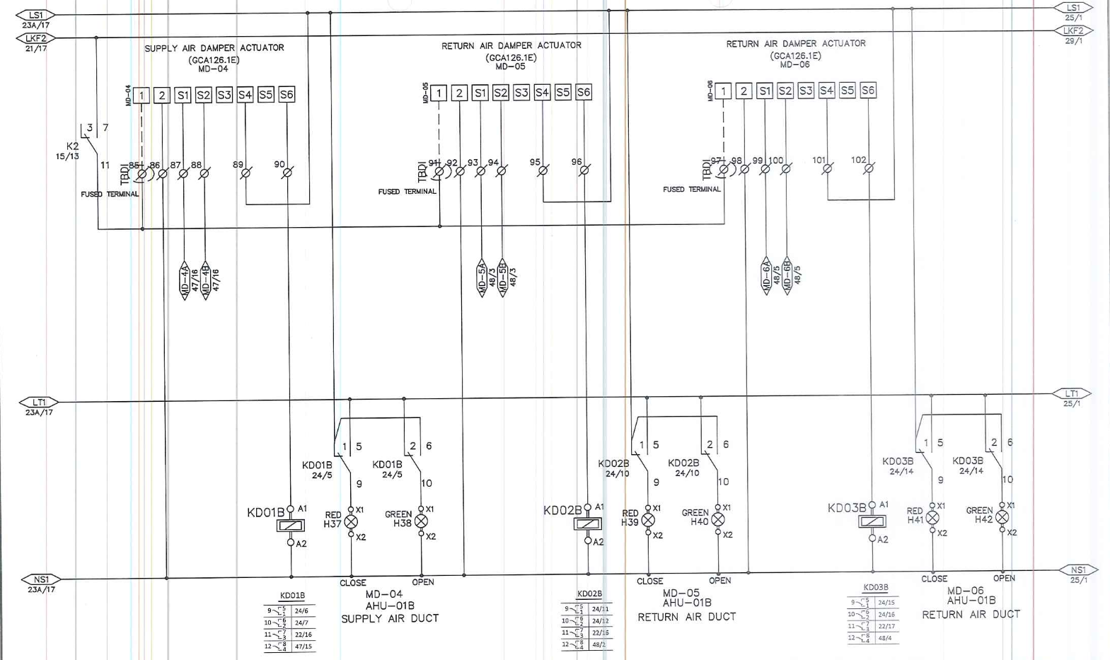
d. Monitoring of ‘Close’ & ‘Open’ status of Motorized Dampers.
e. Monitoring of temperature in the served area and in outside, return & supply air ducts.
Description of HVAC equipment:
The equipment ‘controlled and monitored’ by the HVAC control panel includes,
a. Two(2)AHUs operating as 100% duty/standby units. Each AHU has Two (3) motorized dampers, One (I) in the supply, the One (I) in the return air duct, and One (D) in the fresh air duct.
b. Two (2) Exhaust Fans. Two (2) Exhaust fans in the battery Room.
c. One(D) CFU operating as 100% duty. CFU consists of two (2) fans and 3 motorized damper.
d. An Audio-visual alarm in the battery room (by others).
e. One (I) EDH, one () for the battery room.
f. Gas Detectors in the outside air duct (by others).
g. One each smoke detectors in the outside air duct (by others)
Application of field devices:
The following field devices are utilized to implement the desired logic,
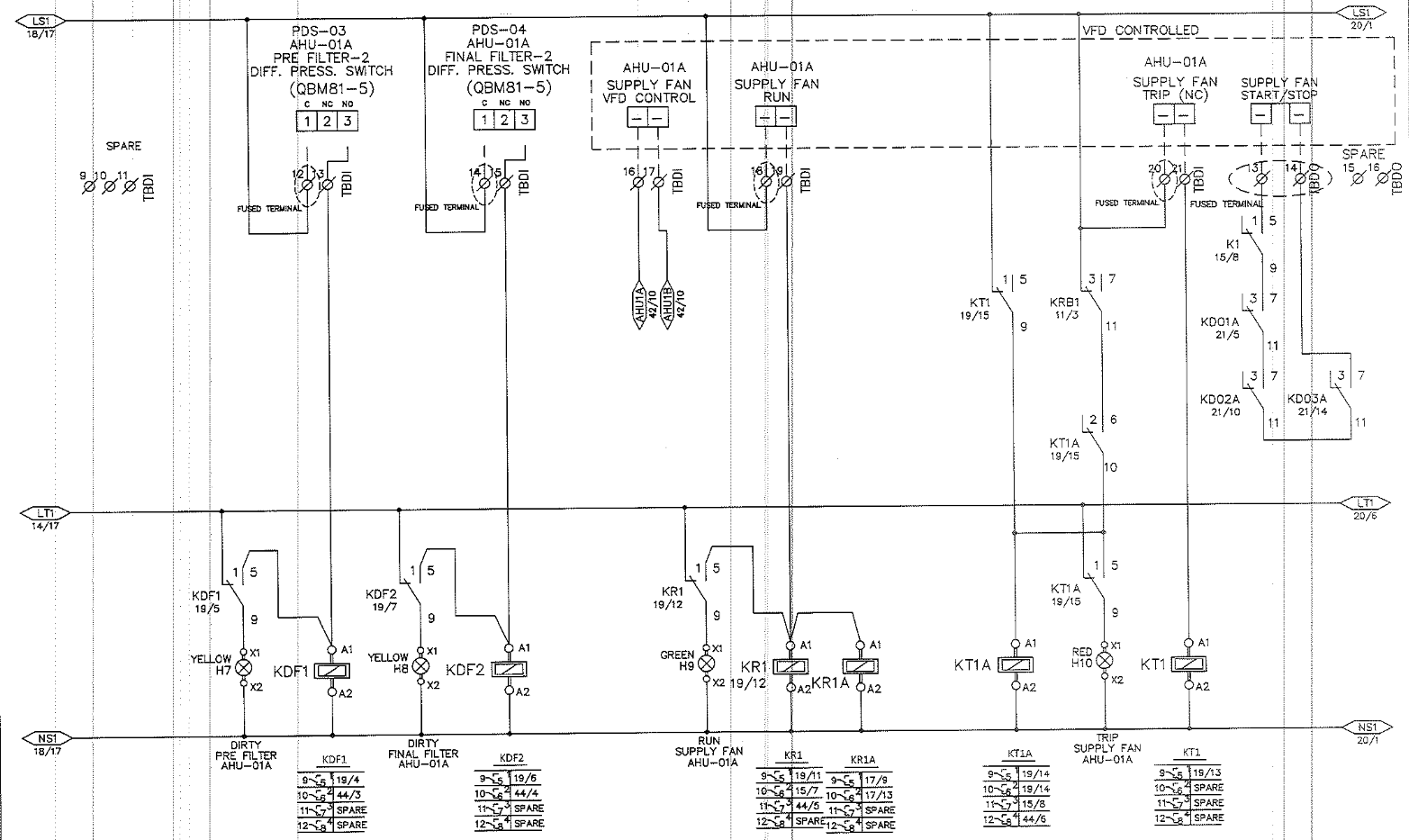
a. Differential pressure switches to monitor the status of filters. The differential pressure switches shall monitor the pressure across the filters, if the differential pressure is beyond the pre-set limits (adjustable) alarms will be energized on the touch screen indicating ‘Dirty Pre OR Bag Filter’.
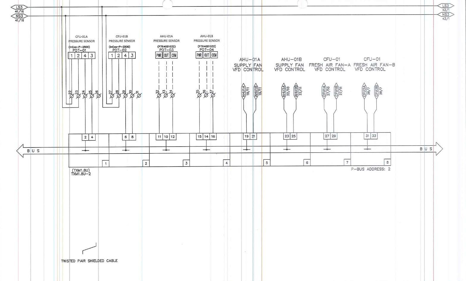
b. Differential pressure sensor to monitor the pressure of the blower fan of AHUs, CFU’s with VFD control.
c. Walls mount temperature sensors to monitor temperature in Served room.
d. Duct temperature sensors to monitor temperature on the duct.
e, Wall mount differential pressure transmitter to monitor the pressure in the served area.
2. Normal operation;
The following sequence describes the operation of the system during normal operating conditions.
Start/Stop of System;
AHU/ACCU
When AHU-1A Motor is in operation, the interlocked two Position motorized Damper in the supply & return ducts are fully open. The respective air filter status of the AHU is also displayed at the DDC Panel. This is typical for the AHU-1B operation. lf the selector switch is set in the “HAND” Position of the respective AIIU, command will be sent to Supply, fresh, and return air damper actuators to open. After confirming the open status of the dampers as mentioned above, The supply fan will energize and the AHU will run continuously provided that it meets all the safety interlocks.
If the selector switch in “OFF” position the respective AHU will stop and all the respective damper are all closed. If the selector switch is set to “AU’TO” position of the respective AHU will a command will be sent to supply and return air damper actuator to open, then by checking the open status of the dampers, the respective A!-IU supply fan will energize and the AHU will nm according to the time schedule and the software program loaded in the DDC controller.
DPS shall monitor are installed across the filters to monitor the pressure across them. When the pressure difference across the respective filter rises above the set point, an alarm (pre-filter dirty or bag filter dirty) shall be raised on the panel fascia (through HMI),
BLEED FAN
For Bleed fan, Bleed fan is provided with three position selector switch HAND”, “OFF” and “AUTO. If the selector switch is set in “HAND” position, the respective bleed fan will run continuously provided it passes the safety interlocks.
If the selector switch is set in OFF” position the bleed fan will stop. If the selector switches is set in “AUTO’ position the bleed fan will run according to the time schedule and the software program loaded in the DDC controller.
CFU
In CFU, CFU’s have a supply and fresh air motorized damper, Each CFU unit has 2 filters. And two(2) fans. Each CFU unit are provided with three position selector switch “MANUAL”, “OFF” and “AUTO
Each CFU unit are electrically interlocked with the supply & fresh air dampers, this means that the supply fan will not run unless these dampers are opened.
MANUAL Position:
If the selector switch is set in “MANUAL” position of the respective CFU unit, command will be sent to supply and fresh air dampers actuators to open, after confirming the open status of the dampers as mentioned above, the CFU unit will run continuously provided that it meets all the safety interlocks.
Off Position:
If the selector switch is set in “OFF position the respective CFU unit will stop and all the respective dampers will be closed.
Auto Position:
If the selector switches is set in “AUTO position of the respective CFU unit, a command will be sent to supply and return air dampers actuators to open, then by checking the open status of the dampers, the CFU unit will run according to the time schedule and the software program loaded in the DDC controller.
In case of trip the respective CFU unit shall shutdown and respective trip alarm shall be shown on the HMI and the standby unit shall operate.
Filters are provided with differential pressure switch, When the pressure difference rises above the set point in the DDC controller, “Dirty filter” Alarm shall pop up on the HMI.
Supply & Fresh Air motorized dampers shall be interlocked with the respective CFU nit, If the CFU unit is de-energizes then its respective motorized dampers shall also get closed.
EXHAUST FAN
The Battery room is served by two exhaust fans. These serve the battery room and operate as all duty and standby units. Air flow switches are installed across each fan to monitor the airlow. The HVAC control panel controls and monitors these two (2) exhaust fans, The HVAC control panel alternates the operation between duty and standby units based on running hours and also when fault is detected in the running fan.
3. Conditions for changeover from duty to standby units:
The standby unit will be automatically operated in event of following faults.
a. When there is fault in duty AHU.
b. Fault is detected in compressors of duty unit.
c. When there is fault in the duty Exhaust fan.
4. Temperature control:
AHU/ACCUs
The duct temperature sensor installed in the supply and return air duct shall measure the air temperature and the measured value will be transmitted to the controller. The measured temperature is compared with the cooling set point. If the measured value is higher than the set point then, the HVAC control panel shall send the command signals to the compressors of the duty AHU to operate in steps until the desired set-point is achieved,
EDH
An Electric Heater is provided in the duct of battery room, rack room and for telecom room, This electric duct heater (EDH) is controlled via Thermostat.
5. HMI/OPERATOR UNIT:
This unit shall be installed in the DDC Panel. It is a Networkable operator unit for viewing and operating one or several Desiga PX Controllers. Through this unit.
Complete Pant information can be viewed like the plant functions, time schedulers, calendars, set-points, current values, etc, We can view all the alarms and it allows us to acknowledge and reset them. The set-points can be changed. Time scheduling can be done. Passwords can be set for users.
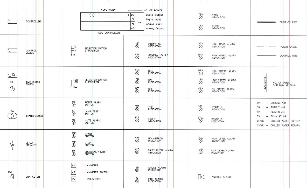
6. Alarms and indications:
The control system is programmed to give an audible alarm signal for system malfunctions. The alarm is set-off when conditions are outside the specified ranges of values and when alarms are detected. This audible alarm can be silenced by pressing the ‘Mute Alarm’ pushbutton on the face of the control panel A ‘lamp test’ pushbutton is provided to test the integrity all the indication lights on the panel.
To reset the alarms a ‘reset alarm’ pushbutton is provided on the control panel. The following signals (dry contacts) will be transmitted to DCS in event of following faults in the HVAC system.
a. HVAC common alarm (dry contact) to DCS, when either or both of duty & standby units have failed. (Fault in AHUs / EFs/ CFU/ BF/ EDH/ Motorized Dampers)
STOP HIGH RATE CHARGING OF BATTERIES & AUDIO-VISUAL ALARM:
When both the exhaust fans of battery room fail, the alarm will be transmitted to battery charger to stop high rate battery charging and the audio-visual alarm (installed outside battery room) will be energized. This could be released by pressing the “mute” pushbutton provided on the panel face.
7. Emergency operation:
Emergency Shutdown Button.
In event of Undefined Emergency Situation, when you press/push the emergency shutdown button the complete system will shut down. In event of Maintenances purposes, you can temporarily shut down the complete system.
Fire Alarm.
In event of fire alarm signal from the fire alarm control panel (FACP), the complete system will shut down. Visual and audible alarm will be energized on the face of the control panel. To resume normal operation, the alarm must be cleared from the field and must be manually re
set from the control panel by pressing the ‘alarm reset’ pushbutton.
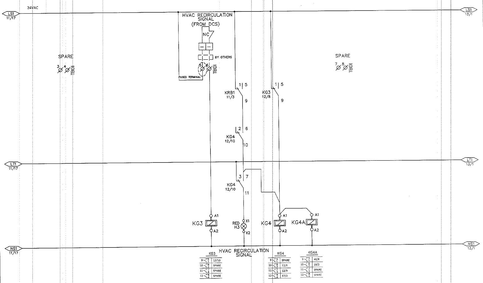
Gas Alarm.
In event of Gas Alarm, all the MFSD shall open position and MGD will be closed and HYAC system will be in recirculation mode. Upon receiving a Gas alarm from DCS the 1-IYAC panel will close MGD and switch HY AC system to recirculation mode, and recirculation mode status will be be reported to DCS.
Upon receiving H2S or combustible gas detection in the Air intake duct. HY AC system shall automatically react as follows:
MGD -01 at the Air intake duct shall be closed.
CFF-01 A/B and EF O I A/B shall be shut down.
AHU-0 I A/B shall continue operation in recirculation mode.
DDC BASED HVAC CONTROL PANEL (Including motor starters for exhausts fan)
")