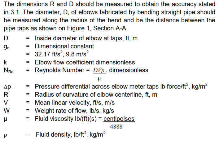
This article is one of Flow Measurement Instrumentation articles. This standard offers a guide for the use of 90° elbows for measuring flow of incompressible fluids. Main keywords for this article are Elbow Taps Flowmeter Design Requirement. Elbow Taps Flowmeter References. Elbow Taps Flowmeter Flow Calculations. ASME Fluid Meters.
Elbow Taps Flowmeter References
Reference is made in this standard to the following documents.
American Society of Mechanical Engineers (ASME)
Fluid Meters, Their Theory and Application, 6th Edition, 1971, pages 232 and 233
Elbow Taps Flowmeter Design Requirement
- Although a calibrated elbow should be just as accurate as an orifice or venturi meter, very little data has been accumulated on elbow flow coefficients and consequently more uncertainty is involved in calculating flow in an uncalibrated elbow meter. An elbow that is uncalibrated but carefully tapped, measured and located according to the criteria set forth in this section is subject to about ±4 percent error; see ASME Fluid Meters, Their Theory and Application. In comparison, orifice meters are subject to about ±2 percent error. Hence, elbow flowmeters should be considered for noncritical flow measurement.
- The advantages of elbow flow meters over other flow measuring devices are that they cost relatively little to fabricate and introduce no additional pressure loss, when suitable elbows are an inherent part of the piping system. The main disadvantage is the greater error involved. In addition, since the pressure differential provided by an elbow meter is generally smaller than that provided by an orifice, more sensitive measurement of pressure is required. Also, significantly greater lengths of straight pipe may be required between an elbow and the nearest upstream and downstream fittings.
- The data presented in this standard are based upon water flow, and may be applied to other incompressible fluids. The pressure differential provided by gas flow generally is too small to make accurate flow measurement practical.
- The elbow chosen for metering preferably should be long radius. R/D > 1.5 The minimum pipe size recommended is 1 1 /2 NPS.
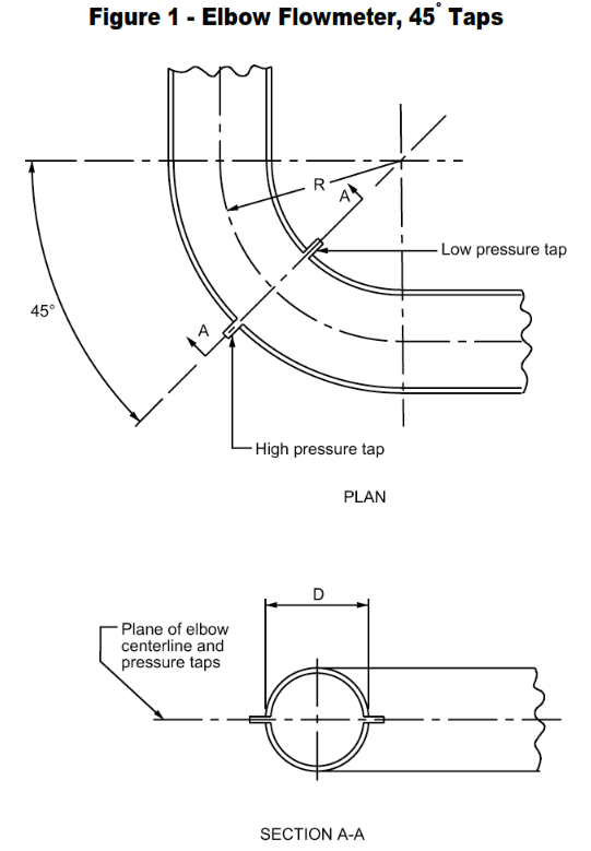
- The pressure taps shall be located 45° from the elbow inlet and in the plane of the elbow centerline, see Figure 1.
- If the plane of the elbow is not horizontal, one pressure tap will be higher than the other tap and there will be a hydrostatic component in the pressure differential. Care shall be taken to see that this component is eliminated by proper use of a differential pressure manometer, or accounted for in the flow calculations.
- Tap holes shall be sized and prepared free of burrs, in accordance Figure 1.
- Location of the elbow selected for metering should be at least 25 pipe diameters from the nearest upstream fitting and at least 5 pipe diameters from the nearest downstream fitting.
Elbow Taps Flowmeter Flow Calculations
The flow rate through an elbow meter is given by: Equation 1

