This article covers all inspection points related to visual, electrical and mechanical inspection of Oil, Vacuum, Gas Circuit Breakers.
Electrical & Mechanical Inspection for Equipment
1. Initial Inspection for Shipping Damage:
- Upon equipment receipt, conduct an inspection to identify any physical damage resulting from shipping.
- Report any such incidents following the shipper’s specified instructions.
(Note: This step ensures that equipment arrives intact and ready for installation.)
2. Verification of Equipment Information:
- Compare the information on the equipment nameplate with the latest single line diagram and equipment specifications.
(Explanation: This is crucial to ensure that the received equipment matches the project requirements.)
3. Orientation of Circuit Breaker:
- Confirm that the circuit breaker is set in the correct orientation for line and load connections.
(Context: Ensuring proper orientation is vital for safe and effective electrical connections.)
4. Safety Grounding Cable Verification:
- Verify that safety grounding cables are correctly connected to the primary incoming power supply terminal point of the facility or construction equipment.
- Ensure that these cables are sized appropriately for the available fault current, following the specifications provided by Electrical Engineering.
- Maintain the connection of safety grounding cables until the electrical equipment commissioning is complete and the facility or equipment is ready for energization.
(Rationale: Proper grounding is essential for safety and protection against electrical faults.)
5. Bushing Inspection:
- Inspect bushings for any signs of damage and remove any blocking materials.
(Importance: Bushings are critical components, and any damage must be addressed to prevent operational issues.)
6. Mechanical and Contact Checks:
- Conduct comprehensive mechanical operation and contact checks on both the circuit breaker and its operating mechanism.
- Refer to the manufacturer’s instruction literature for guidance.
(Significance: These checks ensure the breaker functions correctly and maintains reliable electrical connections.)
7. Wiring Termination Inspection:
- Examine all wiring terminations, including both primary and secondary connections, as well as control wiring.
- Verify that appropriate strike distances for high-voltage conductors are maintained.
(Explanation: Proper wiring is essential for the safe and efficient operation of the electrical equipment. Maintaining safe distances for high-voltage conductors prevents arcing.)
5.3 Operating Mechanism Checks for all Equipment
5.3.1 Breaker Exercise and Closing Verification:
- Actuate the breaker to exercise its operation and confirm that it closes and latches correctly.
(Rationale: This step ensures that the breaker functions as intended and securely closes when needed.)
5.3.2 Mechanism Check per Manufacturer’s Instructions:
- Perform a comprehensive mechanism check following the guidelines outlined in the manufacturer’s instruction literature.
(Importance: Adhering to the manufacturer’s instructions is essential to validate the proper functioning of the equipment’s operating mechanisms.)
Operational and Electrical Testing for All Equipment
1. Conduct the Following Tests:
- Contact Time Travel Test: Measure and record the contact time travel to ensure it falls within acceptable parameters.
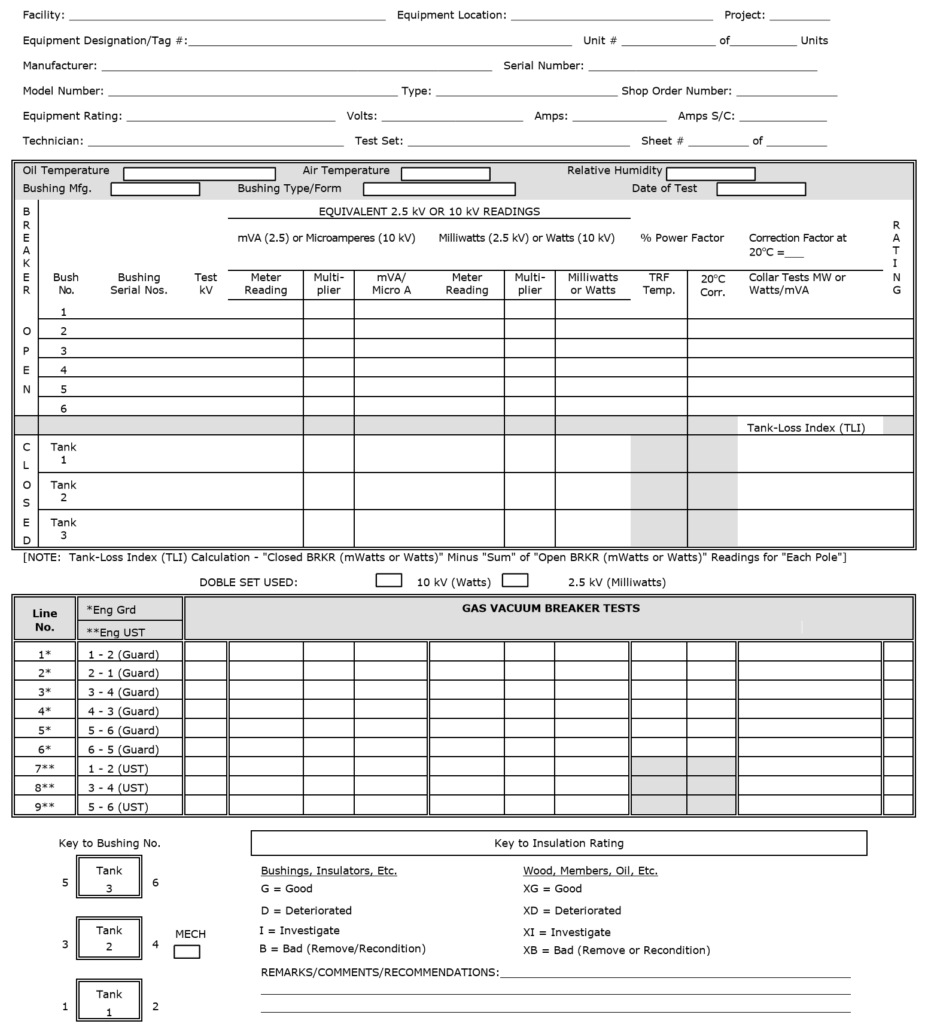
(Reasoning: This test assesses the speed and reliability of the equipment’s contactors.) - Insulation Power Factor (Doble) Bushing Test: Perform a power factor test on the insulation of bushings using the Doble test method.
(Significance: This test evaluates the insulation quality of bushings.) - Insulation Resistance (Megger) Test (Phase-to-Phase and Phase-to-Ground): Measure and record the insulation resistance between phases and from each phase to ground using a Megger tester.
(Purpose: This test verifies the integrity of insulation and detects any potential faults.) - Digital Low Resistance Ohmmeter (Ductor) Test: Determine the contact resistance in micro-ohms (μΩ) using a digital low-resistance ohmmeter (Ductor). Record the results.
(Importance: This test evaluates the electrical integrity of contacts, and results should not exceed 300 micro-ohms (.0003 ohms), per the manufacturer’s specifications.)
2. Function Test of Alarm Devices:
- Perform a function test on all alarm devices, including the alarm panel, to confirm their proper operation.
(Explanation: Ensuring that alarm devices are functioning correctly is critical for safety and monitoring purposes.)
3. Verification of Current Transformer (C.T.) and Potential Transformer (P.T.) Ratios and Polarities:
- Confirm that the C.T. and P.T. ratios and polarities are accurate and aligned with specifications.
(Rationale: Accurate ratios and polarities are crucial for precise measurement and protection functions.)
4. Validation of Mechanical and Electrical Interlocks:
- Verify the complete and proper operation of all mechanical and electrical interlocks, including any key-type systems.
(Importance: Interlocks ensure the safe and coordinated functioning of equipment and systems.)
Vacuum Circuit Breaker Checks
1. Conduct High-Potential Test:
- Perform a high-potential test on each interrupter for a duration of one (1) minute.
(Note: Refer to the manufacturer’s instruction literature for guidance on X-radiation hazards and voltage levels during this test. Record the test results.)
(Explanation: This test assesses the insulation integrity and dielectric strength of the interrupters.)
2. Verify Contact Erosion Tolerances and Contact Travel:
- Ensure that contact erosion tolerances, contact travel, and overtravel align with the manufacturer’s specified values.
- Confirm the initial contact wear position indication.
(Rationale: These checks ensure that the vacuum circuit breaker’s contact system operates within acceptable limits as per the manufacturer’s guidelines.)
For detailed procedures and checks, please refer to the manufacturer’s instruction literature, specifically the installation and maintenance sections, to provide comprehensive descriptions.
SF6 Circuit Breakers Checks
- Pressure Switch Operation Check:
- Ensure that the proper pressure switch operation functions comply with the manufacturer’s specifications for the operating mechanism.
- Record the results for the following pressure switches:
- Governor switch: __ psig (Opens on rising pressure.)
- Low pressure switch: __ psig (Closes on falling pressure.)
- SF6 Gas Filling:
- Fill the breaker with SF6 gas according to the manufacturer’s specifications.
- Record the SF6 gas pressure for each pole:
- Pole 1: __ psig
- Pole 2: __ psig
- Pole 3: __ psig
- Note the ambient temperature: __ °F
- Verify Low SF6 Pressure Alarm/Trip/Block:
- Confirm the proper functioning of the low SF6 pressure alarm/trip/block.
For detailed procedures and checks, please refer to the manufacturer’s instruction literature, specifically the installation and maintenance sections, for comprehensive descriptions and guidelines.
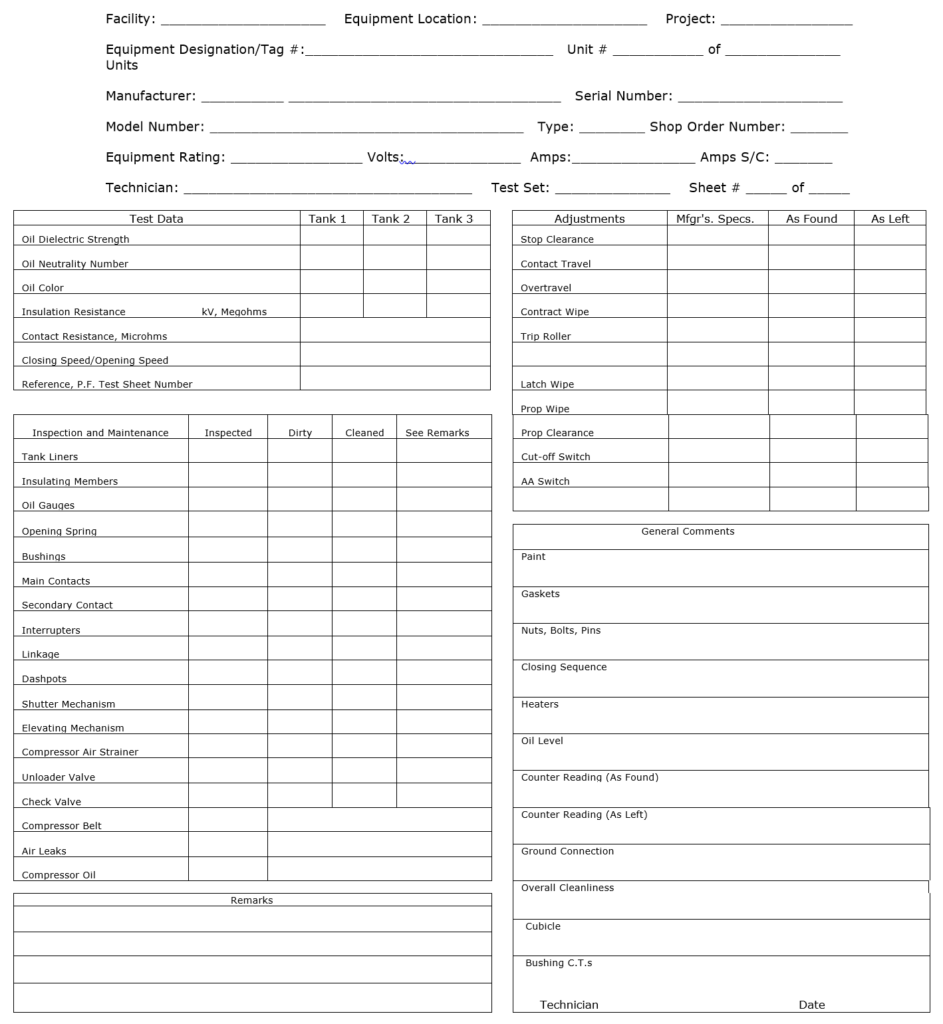
Oil Circuit Breaker Checks
- Verify Oil Levels:
- Confirm that proper oil levels are maintained in bushings and tanks.
- For tanks, ensure the oil level corresponds correctly with temperature changes.
- Oil Dielectric Strength Test:
- Perform the oil dielectric strength test before energizing the breaker. Use one of the following methods based on the specified voltage:
- ASTM D 877 Method: Use 30 kV or above with a 1-inch diameter disc electrode spaced 0.10 inch apart.
- ASTM D-1816/VDE Method: Use 25 kV or above with 1-inch spherical electrodes spaced 0.04 inch apart.
- Record the test results: _____________
For detailed procedures and additional checks, please refer to the manufacturer’s instruction literature, particularly in the installation and maintenance sections, for comprehensive descriptions and recommended procedures.
Relay Panel
- Calibration of Protective Relays:
- Calibrate all protective relays following the latest International Electrical Testing Association (NETA) Acceptance Testing Specification.
- Section 7.9.1 for Electromechanical Relays
- Section 7.9.2 for Microprocessor-based relays
- Adhere to applicable manufacturer’s recommendations.
- Ensure that relay software revisions and setting file software revisions match.
- Utilize Electrical Engineering job-specific relay settings.
- Record the calibration results and send them as left files to Electrical Engineering.
- Secondary-Injection Test:
- Conduct a secondary-injection test on phase current and differential relays at the current transformer terminals.
- Inject sufficient current to ensure the functional operation of all trip devices.
- Primary-Injection Test for Ground Sensing Relays:
- Perform a primary-injection test on any ground sensing relays, including 50GS and 51G types.
- Verification of C.T. Short-Circuiting Scheme:
- Verify that the short-circuiting scheme for current transformers (C.T.) is functional on all current and transformer differential relays.
- Conduct a resistance check at relay case terminals between C.T. common and active C.T. terminals.
- Ensure that all connections are short-circuited to common when the relay is removed from the case.
- Function Testing:
- Functionally test each relay and associated device, including lock-out relays.
- Ensure that all tested components are capable of tripping the circuit breaker, including the circuit breaker control switch and remote circuit trips.
Please refer to manufacturer’s instruction literature and Electrical Engineering guidelines for detailed procedures and additional checks as required.
Documentation Requirements
- Nameplate Data and Test Results:
- Compile and document complete nameplate data information for all relevant equipment.
- Include detailed test results for all conducted tests and calibrations.
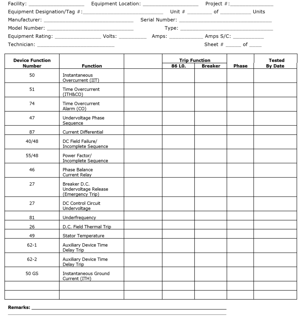
- Electrical Protective Device Verification Report:
- Prepare a comprehensive Electrical Protective Device Verification Report.
- Ensure that the report covers all protective devices and their verification status.
- Include calibration details, test results, and any necessary adjustments.
- Circuit Breaker Test Reports:
- Generate individual test reports for all circuit breakers.
- Include specific test details, results, and any relevant observations or remarks.
- Filing of Documentation:
- Maintain one copy of the completed documentation on-site for future reference and accessibility.
- Forward an additional copy of all documentation to the Electrical Engineering Department for their records and review.
Ensure that all documentation is accurate, well-organized, and readily accessible for future reference and compliance purposes.