ELECTRICAL TEST TRANSFORMER
Transformer Turns Ratio (TTR) of Transformer
Transformer “turns ratio” must be identical for each phase.
The Turns Ratio = N1/N2 = V1/V2 = I2/I1 = K
Where: N1 = Number of turns of primary windings
N2 = Number of turns of secondary windings
V1 = Primary Voltage (line to line)
V2 = Secondary Voltage (line to neutral)
I1 = Primary Current
I2 = Secondary Current
Turn ratio K = V/V2/√3 = √3 V1/V2 For three phase.
K = V1 / V2 For single phase.
Procedure:
a.) For this test must be conducted between HV winding & LV winding.
b.) For Δ-Y transformer, this test must be conducted between HV winding (line to line) and LV winding (line to neutral).
c.) This test shall be conducted for each winding and all tap setting.
d.) The test value should be noted as under:
Acceptable value:
Turns ratio test result should not deviate more than 0.5% form either the adjacent coil or calculated ratio.
Winding Resistance Test of Transformer
Theory: Resistance of any electrical circuit can be expressed as follows:
R = V/I
Where V = Applied DC voltage
I = Measured DC current
R = Calculated winding resistance in ohm.
Procedure:
For this test, test kit should be connected for both winding in primary and secondary side.
If primary connection between U-V, the Sec. Connection will be between U-V
” V – W “ V – W
“ W – U “ W – U
For single-phase transformer, this connection should be made between (H-H0) and (X-X0)
Acceptable Value:
Winding resistance test results should compare within one percent (1%) of adjacent windings.
Megger Test / Insulation Resistance & Polarization index Test of Transformer
Procedure:
a.) Insulation resistance test should be performed between winding to winding and winding to ground for both LV & HV windings.
b.) Test duration shall be 01 minute.
c.) Test connection shall be made as follows:
1.) HV – LV + GND,
2.) LV – HV + GND,
3.) HV + LV – GND
d.) Test result should be multiplied by the temperature correction factor.
e.) For calculating the polarization index, then test duration shall be 10 minutes and calculate the polarization index as follows: P.I. = 10 Minutes reading / 1 Minute reading
- HV To LV + Ground 2. LV To HV + Ground
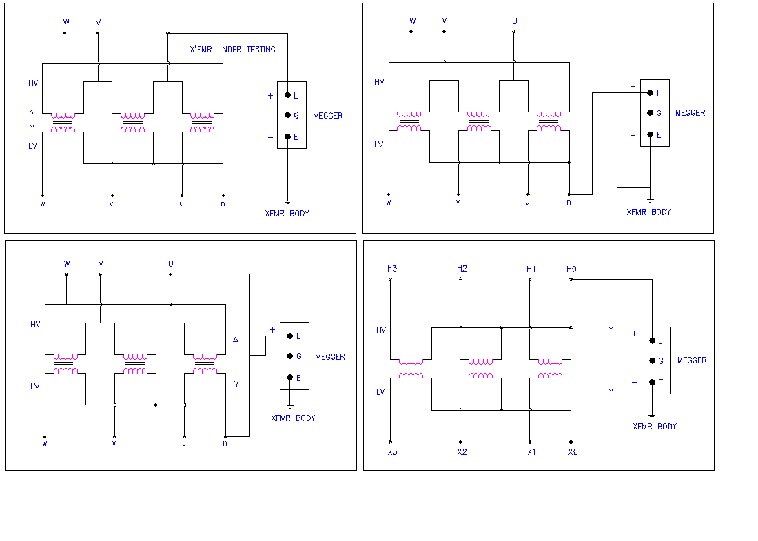
- HV + LV To Ground 4. For Y – Y Transformer HV + LV To Ground
(Connection Diagram for Transformer Insulation Test)
Winding Temperature Indicator with Contact of Transformer
- To ensure the current transformer and matching unit or matching resistance has been used as per the approved drawing.
- Verify the current transformer rating.
- For conducting the electrical test require primary injection test set.
- Disconnect all the contact wiring of the WTI.
- Set the contact of the WTI at certain temperature as per the manufacturer instruction manual and procedure.
- Connect the power supply to the primary current injection test set.
- Connect a continuity tester across the seted NO contact of the WTI.
- Connect current terminals of the test set to current transformer primary terminals.
- Gradually increase the current until the contact close, but do not increase the current more than the current transformer rating.
- Record the reading current and temperature indicator and compare with the manufacturer instruction manual. If the reading is not require to calibrate the WTI. Follow the calibration procedure.
- Calibration is based on information (from heat run test) about the gradient (difference between winding and top oil temperature) and the corresponding output from the current transformer. Graph WT001 indicates current required through the heating element to give a corresponding gradient. The current to the heating element can then be calibrated with matching element or matching unit to this value calibration is only necessary for one known relation between loads and gradient.