This article is about mechanical running and functional test of elevator as well as tests are required for Elevator factory acceptance test which is called Elevator FAT test also.
Elevator Factory Acceptance Test FAT
MECHANICAL RUNNING TEST AND FUNCTIONAL TEST
Test will be performed nearly to ASME 17.1, Para 8.10.1 and 8.10.2.
Dimension check according to default
Control and capture of the mass marked in the drawing of the elevator car.
Drawing number “1023899” (see in the appendix)
___________ .mm
___________ .mm
___________ .mm
___________.mm
Control and capture of the mass marked in the drawing in the lift.
Drawing number “1023892 B” (see in the appendix)
___________ .mm
___________ .mm
___________ .mm
___________.mm
Paint color
Control the paint color reference to the “RAL Color Formula Guide”. Refer to Paint Specification of project drawings.
Car roof with hatch/emergency exit check
Expected result:
The mechanical function of the interlocking and hatch should be easy. The hatch can be fully opened. Mechanical function test of the hatch lock and trapdoor.
Check the emergency stop circuit
Expected result:
For all test points included, when activated the emergency stop circuit must be interrupted and the lift disabled. Function test of the emergency circuit and safety device limit-switch
TEST INSTRUCTIONS
-Check the emergency stop circuit
-Check the safety device limit-switch
All functions must be guaranteed in accordance with the applicable wiring diagram
1. Shaft pit: Control panel with the Emergency stop button is located in the lower enclosure
2. Return control: Emergency stop button on the control panel in the switch cabinet in the lower enclosure to return the lift in an emergency.
3. Landings: Limit switch for the landing door that interrupts the emergency stop circuit in the event of an open landing level door.
The limit switches are not available during the test and are simulated using a bridge in the switch cabinet.
4. Main switch cabinet: Emergency stop button in the lift switch cabinet
5. Dummy plug, external controls: When this dummy plug is removed from the lift switch cabinet, the emergency stop circuit is interrupted.
The plug is required to connect the overspeed safety brake control to test the overspeed safety brake during the function test of the lift.
6. Emergency limit Up/Down: The limit switch installed on the lift (lx up, lx down) that is activated at the lower and upper limit positions on the tower.
7. Overspeed safety brake: The limit switch on the overspeed safety brake that is activated when triggered and can only be mechanically enabled again.
8. Roof hatch interlocking: Limit switch in the trapdoor interlocking that monitors the status of the lock.
9. Trapdoor: Limit switch on the trapdoor that monitors the status of the door.
10. Trailing cable (optional): If there is an excessive tensile load on the Trailing cable, a limit switch integrated in the emergency stop circuit is activated by the monitoring and the lift is disabled.
11. Cabin door 1: When opening the door, the emergency circuit is interrupted and all functions of the Elevator prevented. The elevator does not work.
12. Cabin door 2 (optional): Refer to cabin door 1
13. Cabin door 3 (optional): Refer to cabin door 1
Signalling unit of ground station (optional)
Check horn, light and potential-free alarm contact (activated by an alarm button in the car) !
Electrical door interlocking safety lock
Expected result:
The car door must not be able to be opened during movement and is locked by the safety lock. Check the locking of the car door 1 and (car door 2, 3 optional) during movement.
Mechanical Emergency unlocking of the car door
Expected result:
In the event breakdown of the main power supply, the locked car door must be able to be opened using a triangular key.
Check the mechanical unlocking of car door 1 and (car door 2, 3 optional)
Electrical Emergency unlocking of the car door
Expected result:
In the event breakdown of the main power supply, the emergency unlocking of the car doors must be possible at enabled landing. Check the electrical unlocking of car door 1 and (car door 2, 3 optional).
Check the emergency power supply
Expected result:
In the event breakdown of the main power supply, emergency functions of the lift control are maintained by a UPS cable.
Disconnect the lift from the main power supply (disconnect the mains plug)
-Emergency light must automatically switch on
-Emergency unlocking of the car doors must be possible at enabled landing.
Lowering brake, mechanical
Expected result:
In the event breakdown of the main power supply, the lift brake can be released using the lower pedal installed in the car and the car can descend to the next landing. Move to the highest landing without load, fully depress the lower pedal (see in Operating Manual), the lift slowly moves downwards.
Lowering brake, electrical
Expected result:
In the event breakdown of the main power supply, the button “Start emergency lower” can be used to automatically lower the car to the next landing.
Move to the highest landing without load and disconnect the lift from the main power supply (disconnect the mains plug).
Activate key switch lower mode On and press the button Start emergency lower.
The automatic lowering to the next landing will start after pressing button in approx. 3sec.
Dynamic test of the overspeed safety bra
In accordance with EN 81 (currently valid version)
Expected result:
In the event of a failure of the motor brake or gearbox etc., the lift must automatically stop using the overspeed safety brake.
During the test, load with 125 % of the rated load.
The test load must be entered in the test report. Observe the rated load specifications on the rating plate.
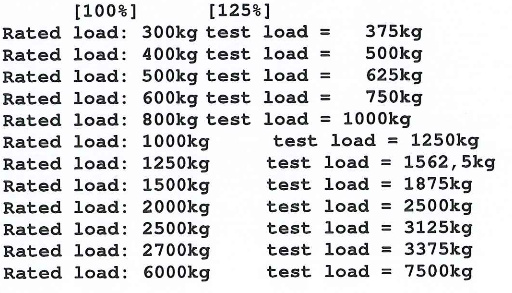
Enter test load: ———————-kg. Repetition max. 3 times.
To test the overspeed safety brake, the dummy plug in the switch cabinet must be removed and the overspeed safety brake control must be connected.
Now the lift is moved to the highest position on the test tower. The lift brake is deactivated by pressing two buttons on the overspeed safety brake control and the lift moves downwards. When a specified speed is attained, the overspeed safety brake automatically activates and stops the lift.
To release the overspeed safety brake, the lift must be moved upwards.
ATTENTION! The brake must be reset after each drop test.
Noise level measuring inside the cabin
Measured noise level within the cabin during the driving operation.
Nominal value: ———–dB/A
Actual value:————–dB/A
Speed measurement of Hoist
Nominal value:=========m/min
Verification of hoist speed.
Actual value:==============m/min