This article is about EMT & FMC Fittings and Accessories Material Selection and Types for commercial buildings, plants and refinery projects as per international codes and standards. EMT and FMC fittings shall be listed as complying with UL 514B. [NFPA 70, NEC 358.6 & 348.6]
EMT & FMC Fittings and Accessories Material Selection
| New and Unused – Electrical materials shall be new and unused. |
| As Designed – Electrical materials shall be in accordance with the Saudi Aramco-approved project-specific design drawings, diagrams, schedules, lists, databases, and associated documents (in particular, raceway type and trade size as shown on electrical BOM and raceway schedules). |
| QC Before Installation – Electrical materials shall conform to all applicable requirements, standards, and specifications prior to release to be used as part of the work. |
| Identification – Electrical materials shall be identified by using tags, stamps, color coding, stencils or labels. The location and method of identification shall not affect the function or quality of the materials. |
| Traceability – Electrical materials shall be traceable from the manufacturer and supplier through delivery, storage, fabrication, erection, installation, repair, modification and use. |
| Marking: Units of measure for markings shall be in SI (metric), equivalent units, or both. [UL 514B Sec. 7.1.1] |
| Marking: All markings shall be legible. All product markings shall be permanent. The following types of markings or the equivalent are permanent: a) etched b) molded c) die stamped d) paint stenciled [UL 514B Sec. 7.1.2] |
Marking: A fitting shall be marked with the manufacturer’s name, trademark, or other descriptive marking identifying the organization responsible for the product. The fitting shall also be marked with a catalog number or an equivalent designation. The marking shall be located where it is readily visible after the fitting has been installed. If the catalog number or its equivalent designation is not marked on the fitting it shall be marked on the smallest unit shipping carton or other container in which the fitting is packaged. [UL 514B Sec. 7.1.3]
| Marking: When a manufacturer produces or assembles FITTINGS at more than one factory, each finished product shall have a distinctive marking to identify it as a product of a particular factory. [UL 514B Sec. 7.1.4] |
| Marking: A FITTING that has been found usable for specific conditions of installation, for use with a specific cable or conduit construction, or for use with certain wiring systems, shall be marked to indicate the condition of installation or the intended use on the smallest unit carton. Table 19 specifies the condition of use and the associated carton marking. [UL 514B Sec. 7.1.5] |
| Marking: Where specific assembly techniques are required for a FITTING, instructions for proper assembly shall be provided with the FITTING when shipped from the factory. [UL 514B Sec. 7.1.6] |
| Marking: Unless specifically required on the product by this standard, required markings shall be incorporated either on the product or on the smallest unit shipping carton. When applicable, the marking specified in Table 19, in the complete or abbreviated form, shall be used. [UL 514B Sec 7.1.7] |
| Marking: A FITTING intended for use with electrical metallic tubing of the 2-1/2 (63), 3 (78), 3-1/2 (91), or 4 (103) trade size shall be plainly and permanently marked “EMT ONLY”, unless the FITTING is also intended for use with rigid conduit and IMC or IMC. This marking shall appear on the fitting. [UL 514B Sec. 7.3.1] |
| Marking: A THREADLESS FITTING intended for use with EMT for wet-location uses shall be marked to indicate such use. [UL 514B Sec. 7.3.2] |
| Marking – BUSHINGS for Flexible Metal Conduit FITTINGS: For a FITTING for flexible metal conduit, as described in Clause 5.4.3.2, the carton shall be marked “Armored Cable BUSHING Required on Flexible Metal Conduit” or with equivalent wording. [UL 514B Sec. 7.19.1] |
| Wall Thickness: A FITTING shall have a wall thickness not less than that specified in Table 16 (Attachment 1) when measured not less than 3.2 mm (1/8 in) from the edge of the FITTING. Where a taper is provided to facilitate withdrawal of the part from the die, the thickness shall not be less than that required at the base of threads when measured 0.8 mm (1/32 in) from the edge of the FITTING. [UL 514B Sec. 5.1.1.1] |
| Zinc Die-Casting Material: The part of a zinc die-cast FITTING that is secured to flexible conduit by insertion inside the conduit shall have a minimum thickness of 0.64 mm (0.025 in). [UL 514B Sec. 5.1.2.1] |
| Coatings on Metallic Surfaces: A ferrous metal FITTING shall be protected against corrosion with a zinc coating not thinner than as specified in Table 17 (Attachment 2) or with an alternate corrosion-resistant coating. [UL 514B Sec. 5.1.3.1] |
| Mechanical Protection: A FITTING shall be constructed to allow assembly to a cable or raceway as intended without damaging the cable or raceway. A part of a FITTING that makes contact with an insulated conductor shall be smooth and rounded. [UL 514B Sec. 5.3.1] |
Mechanical Protection: When a FITTING is intended for more than one trade size of raceway, the internal cross-section area shall comply with the requirements of Clause 5.10.2.1 for the larger size of raceway. [UL 514B Sec. 5.3.2]
Throats and End Stops for FITINGS:
- Other than a COUPLING or LOCKNUT a conduit FITTING shall be provided with a positive end stop for the conduit and a smooth,
rounded throat to protect against abrasion of insulation on conductors entering the FITTING from the conduit. The throat shall be continuous around the circumference of the FITTING. - A FITTING for the connection of conduit shall have a smooth rounded inlet hole. Unless otherwise indicated, the throat diameter of the inlet hole shall be as specified for a BUSHING in Table 1 (Attachment 3).
- The throat of a FITTING that is internally threaded for attachment to rigid metal conduit or intermediate metal conduit, other than a COUPLING or a LOCKNUT (see Clause 5.4.1.1), shall have a throat diameter as specified in Table 1 (Attachment 3) for a BUSHING. The gauges illustrated in Figure 1 (Attachment 4) and the dimensions specified in Table 2 (Attachment 4) shall be used to determine whether the FITTING complies.
- A FITTING shall substantially close the opening with which it is used when the cable or raceway is clamped in place and shall inhibit the passage of a 4.8-mm (3/16-in) diameter probe. [UL 514B Sec. 5.4]
End Stops for Fittings for Flexible Metallic Tubing:
A FITTING for flexible metallic tubing shall be provided with a smooth, rounded end stop with maximum and minimum inside diameters as specified in Table 4 (Attachment 7), and which completely encircles the end of the tubing when installed. These dimensional requirements do not apply to the shoulder of a fitting that is secured by insertion inside the tubing. The maximum external diameter of a flexible metallic tubing fitting that fits inside a raceway (screw-in type) shall not exceed the diameter specified in Table 5 (Attachment 8). [UL 514B Sec. 5.4.5]
| A CONDUIT BODY shall have a cross-sectional area not less than that specified in Table 40 (Attachment 9), based on the largest size raceway that is intended to be connected to it. [UL 514B Sec. 5.7.1.2] |
| A CONDUIT BODY having provision for the connection of conduit or tubing larger than the 1/2 (16) trade size: a) Shall have a removable blank cover, and b) Shall comply with Clauses 5.7.1.4 and 5.7.1.5. This requirement does not apply to a CONDUIT BODY marked for use only with No. 6 AWG (13.30 mm2) or smaller conductors. [UL 514B Sec. 5.7.1.3] |
| A CONDUIT BODY that does not change the direction of wiring passing through it shall have a length not less than eight times the trade size of the connected largest tubing or conduit. [UL 514 Sec. 5.7.1.4] |
| Mating surfaces of a cover and body shall provide a close fit. A gasket, where required to provide a tight fit, shall be provided with the cover. The gasket shall not be required to be cemented or otherwise secured in place on the cover. [UL 514 Sec. 5.7.1.8] |
| Offset FITTINGS: An offset FITTING intended to change the position of the axis of a raceway system shall have a removable cap or cover to facilitate the installation of wires when the offset is greater than 25.4 mm (1 in) or when the axis of the offsetting section is at any angle greater than 35 degrees from the axis of the raceway. [UL 514B Sec. 5.10.1] |
ANGLE FITTINGS:
- A FITTING, such as an offset NIPPLE or ELBOW, through which wires pass shall have an internal cross-sectional area at all points not less than 80 percent of that of a BUSHING having a minimum throat diameter in accordance with Table 1 (Attachment 3). The shape and area of the FITTING shall not inhibit use of the largest number and size of conductors intended for that trade size FITTING.
- ANGLE FITTINGS without removable covers, other than CONNECTORS which are secured to the raceway by means other than turning, shall comply with the wire pull test described in Clause 8.4. These requirements do not apply to FITTINGS for a liquid-tight flexible conduit or flexible cord.
[UL 514B Sec.5.10.2]
| NIPPLES: A NIPPLE shall have a tightening means that has a maximum diameter not exceeding that of a LOCKNUT or BUSHING, as specified in Table 1 (Attachment 3). [UL 514B Sec. 5.15] |
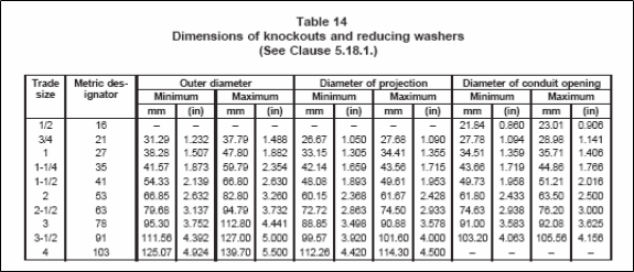
| Reducing Washers: Reducing washers for reducing the size of knockout holes shall be of metal and consist of two pieces with a combined thickness of not less than 1.3 mm (0.052 in) for steel and 2.3 mm (0.091 in) for aluminum. The dimensions of the washers are given in Table 14 (Attachment 10). [UL 514B Sec. 5.18] |
| A CONDUIT LOCKNUT shall be provided with notches or the equivalent to facilitate tightening. [UL 514B Sec. 5.19.1] |
| A CONDUIT LOCKNUT shall have dimensions as specified in Table 1 (Attachment 3). [UL 514B Sec. 5.19.2] |
| A CONDUIT LOCKNUT shall be threaded throughout its entire length. [UL514B Sec. 5.19.3] |
International Codes & Standards
| 1. SAES-P-104 – Wiring Methods & Materials. |
| 2. UL 514B – UL Standard for Safety for Conduit, Tubing, and Cable Fittings. |
| 3. SAES-P-100 – Basic Power System Design Criteria. |
Table 16 – Wall Thickness of Fittings – UL 514B
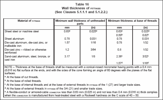
Table 17 – Thickness of Zinc Coating – UL 514B
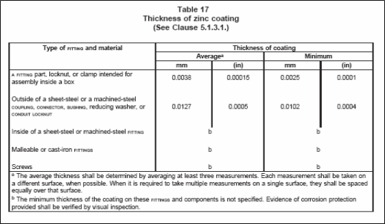
Table 1 – Thickness and Diameters of Locknuts and Bushings – UL 514B
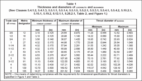
Figure 1 – Hardened Tool Steel Gauges for Throats and Fittings – UL 514B

Table 2 – Diameters of Limit Gauges for Throats of Bushings – UL 514B
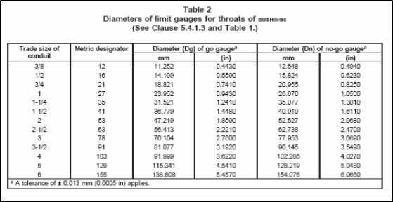
Table 3 – Internal Diameter of End Stop of Flexible Metal Conduit Fitting – UL 514B
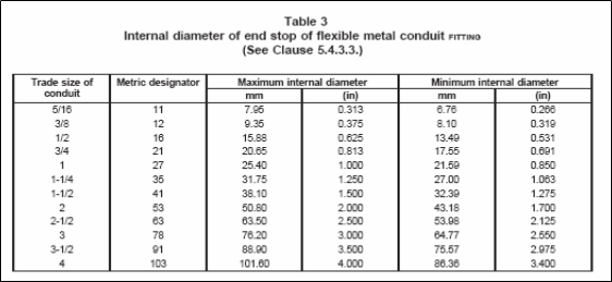
Table 4 – Internal Diameter of End Stop of Flexible Metallic Tubing Fittings – UL 514B
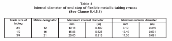
Table 5 – External Diameter of Flexible Metallic Tubing Fittings – UL 514B
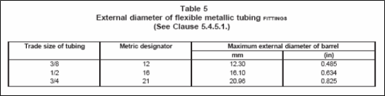
Table 40 – Cross-Sectional Area of Conduit Bodies – UL 514B
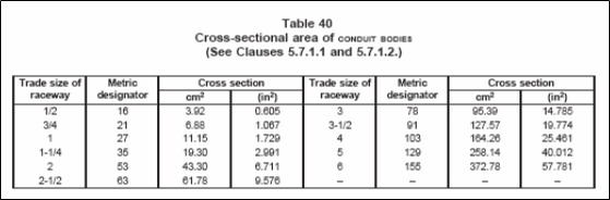
Table 14 – Dimensions of Knockouts and Reducing Washers – UL 514B