This article is about GRS Fittings and Accessories Material Selection Guide & Technical Specification for commercial buildings, plants and refinery projects as per international codes and standards.
Factory GRS elbows, GRS couplings, and associated GRS fittings shall be third-party listed as meeting the requirements of UL standards (UL 514A and UL 514B) as applicable, or approved equal standards). [NFPA 70, NEC 344.6 and Annex A]
GRS Fittings and Accessories Material Technical Requirements & Specification
Conduit and threaded conduit fittings shall have tapered (NPT) threads in accordance with ANSI/ASME B1.20.1.
GRS Conduit Fittings:
Conduit fittings for outdoor rigid steel conduit and liquid-tight flexible metal conduit shall be cast or forged steel, cast iron or malleable iron, either hot-dip galvanized (preferably), or zinc electroplated as supplied by the manufacturer. No aluminum fittings or fitting accessories such as covers, sealing fitting plugs, etc., shall be used outdoor. Only malleable iron sealing fittings shall be used. Gray cast iron split type (EYSR) retrofit sealing fittings may be used if required for repair purposes.
Exception:
Rigid steel conduit and liquid-tight flexible metal conduit hubs manufactured from zinc, that are UL or CSA listed (e.g., Myers Scru-Tite hubs) are also acceptable.
Conduit fittings for rigid steel conduit and liquid-tight flexible metal conduit used above ground in severe corrosive environments shall be as specified in Paragraph 8.9.1 (Item B2 above), and in addition, shall be protected by one of the following methods:
a) Factory-coating with PVC (minimum thickness of PVC: 40 mils) per
NEMA RN 1. Internal surfaces of PVC sleeves (boots) and other
mating PVC surfaces shall be coated with PVC patching compound
(1000421977). Uncoated plugs and other bare metal shall be coated
with PVC patching compound, or with SAES-H-101 APCS-22
(offshore), or APCS-26 (onshore).
b) Field-coating prior to installation in accordance with SAES-H-101
APCS-22 (offshore), or APCS-26 (onshore). Light (sweep)
sandblasting is required prior to coating so that the zinc is not
removed. After installation, any bare metal must be touched up
using either of the above coatings, without sandblasting.
c) By heat-shrinkable tubes or wrap-arounds, where the geometric
configuration permits it.
Exception:
Red leaded brass or silicon bronze conduit fittings may be used as an alternative to the above in severe corrosive environments (only above ground).
| As Designed – Electrical materials shall be in accordance with the Saudi Aramco-approved project-specific design drawings, diagrams, schedules, lists, databases, and associated documents (in particular, raceway type and trade size as shown on electrical BOM and raceway schedules). |
| Free of Damage – Electrical materials shall be free of damage. |
| QC Before Installation – Electrical materials shall conform to all applicable requirements, standards, and specifications prior to release to be used as part of the work. |
| Identification – Electrical materials shall be identified by using tags, stamps, color coding, stencils or labels. The location and method of identification shall not affect the function or quality of the materials. |
| Traceability – Electrical materials shall be traceable from the manufacturer and supplier through delivery, storage, fabrication, erection, installation, repair, modification and use. |
| A fitting or an entry in a cast metal box when assembled as intended to a raceway shall not damage the raceway or decrease the internal diameter of a circular raceway by greater than 15%. The fitting or box entry shall not crack or break, and a securement screw or nut shall not strip when the torque specified in Table 2-1 (Attachment 12) is applied. [NEMA FB1 Sec 2.1.2.2] |
| A part of a fitting or an entry in a cast metal box that is able to contact an insulated conductor shall be smooth and rounded. [NEMA FB1 Sec 2.1.2.3] |
An entry to a fitting or in a cast metal box for use with conduit or tubing shall have a smooth rounded inlet hole and throat. A threaded entry in a cast metal box or in a conduit body shall also comply with the following:
- The depth of the throat in a threaded entry, as measured from the
start of the first thread to the end stop or integral bushing shall comply
with Table 5-3 (Attachment 1). - A threaded entry in a box that does not contain an end stop or integral
bushing shall be threaded all the way through the wall of the box. The
minimum wall thickness at the tapped hole for conduit shall comply
with Table 2-7 (Attachment 2).
NOTE—See Table 5-6 (Attachment 3) for the maximum number of threads in the wall of a cast metal box having through-threaded entries, to allow for the installation of a separate bushing.
[NEMA FB1 Sec 2.1.2.4]
A fitting or a threadless entry in a cast metal box for use with non-flexible metal conduit, or tubing, other than a coupling or locknut, shall be provided with a positive end stop. The throat shall be continuous around the circumference of the fitting and have a diameter as specified in Table 2-2 (Attachment 4). [NEMA FB1 Sec. 2.1.2.5]
Connectors:
- Fittings that are intended to connect to an unthreaded opening in a
metal box or enclosure shall provide reliable mechanical and
electrical connection in accordance with 2.1.2 and 2.1.6, when
assembled to various types, and thickness of metal representing the
range of boxes and enclosures. The range of metal thickness is
specified in Table 2-5 (Attachment 6). - Fittings that are intended to connect to an unthreaded opening in a
box or enclosure shall be provided with a securement means. A fitting
provided with a locknut shall have a thread projection, when
measured from the shoulder stop to the end of the threads along
the major axis of the threaded projection, not less than specified
in Table 2-6 (Attachment 7). - A connector with external taper threads need not be provided with a
locknut. The thread projection, when measured from the shoulder
stop to the end of the threads along the major axis of the threaded
projection, shall be not less than that specified in Table 2-6
(Attachment 7).
[NEMA FB1 Sec. 2.2.3]
| Connectors: 4. A connector with non-interchangeable internal threads, which utilizes a male bushing to secure the CONNECTOR to the box or enclosure, shall be provided with the bushing (see 5.1 exception). 5. A connector or conduit locknut shall substantially close the opening in a box or enclosure with which it is intended to be used when the raceway is secured in place. Compliance is checked using a 4.8 mm (3/16 inch) diameter probe. See Table 5-7 (Attachment 8). 6. A locknut that is supplied as part of a fitting assembly shall be evaluated with the fitting to which it is supplied. [NEMA FB1 Sec. 2.2.3] |
| Cast metal outlet boxes, conduit bodies, junction boxes, and pull boxes, when assembled as intended with appropriate covers, shall have no substantial openings. [NEMA FB1 Sec. 2.3.1] |
| Conduit Bodies Used as Fittings: A Conduit Body, when intended for use solely as a fitting and not as a pull box, junction box, or a device box, shall comply with the requirements for a fitting. [NEMA FB1 Sec. 2.3.2] |
| Conduit Bodies Used as Boxes: A Conduit Body, when intended for use as a pull box, junction box, or a device box, shall comply with both the requirements for a fitting and for the type of box for which it is intended to be used. [NEMA FB1 Sec. 2.3.3] |
| Threaded Entry Construction – Through Tapped Holes: A threaded hole for the connection to conduit that is tapped completely through the wall of a box shall permit proper attachment of a conduit bushing to wrench-tightened conduit. The box shall have a wall thickness in an area where tapped holes are provided or intended for field drilling and tapping that complies with Table 2-7 (Attachment 2). [NEMA FB1 Sec. 2.3.4.1.1] |
Offset and Angle Fittings:
An offset fitting, that is intended to change the position of the axis of a raceway system, shall have a removable cap or cover to facilitate the installation of wire when the offset is greater than 25.4 mm (1 inch) or if the axis of the offsetting section is at any angle greater than 35 degrees from the axis of the raceway. Except as covered in 3.1.3.2, the minimum radius of bend shall be as specified in Table 3-2 (Attachment 9). [NEMA FB1 Sec. 3.1.3.1]
Offset and Angle Fittings:
An angle fitting described in 3.1.3.1, having a radius of bend less than that specified in Table 3-2 for the trade size of raceway for which the fitting is intended, shall have a removable cap or cover to facilitate the installation of wires. The fitting shall be so designed so that wire insulation will not be damaged during wire pulling. Compliance is to be determined by the Wire Pull Test in UL 514B.
This requirement does not apply to a fitting for use with liquid-tight flexible conduit, flexible cord, or to an elbow intended to be used as a connector, that changes the direction of the wires entering it not more than 90 degrees, and, is secured to the raceway system by means other than turning.
[NEMA FB1 Sec. 3.1.3.2]
| Offset and Angle Fittings: Fittings, such as angle connectors, offset nipples, elbows, and so forth, which change the direction of a raceway or cable assembly shall have an internal cross-sectional area at all points not less than 80 percent of that provided by a bushing having a minimum throat diameter in accordance with Table 2-2 (Attachment 4). [NEMA FB1 Sec. 3.1.3.3] |
| Fittings for Use with Flexible Metal Conduit – Assembly and Mechanical Protection: A connector for flexible metal conduit shall have a smooth well-rounded end stop that completely encircles the end of the conduit. The diameter of the end stop shall be within the limits indicated in Table 2-2 (Attachment 4). [NEMA FB1 Sec. 3.2.2.1.1] |
| Fittings for Use with Flexible Metal Conduit – Assembly and Mechanical Protection: A flexible metal conduit fitting which assembles to the inside of the conduit (screw-in type) in the 3/8 (12), 1/2 (16), or 3/4 (21) trade size shall not exceed the diameter given in Table 3-3 (Attachment 10) [NEMA FB1 Sec. 3.2.2.1.2] |
| Fittings for Use with Flexible Metal Conduit – Assembly and Mechanical Protection: Direct bearing screws used in a connector for flexible metal conduit shall not be smaller than No. 10 and shall be of the tangential type (See Figure 3-1, Attachmnet 11). A set screw of the radial type (see Figure 3-2, Attachment 11) can be used provided that the angle between the axis of the screw and the axis of the conduit is not more than 60 degrees. [NEMA FB1 Sec. 3.2.2.1.3] |
| Fittings for Use with Flexible Metal Conduit – Assembly and Mechanical Protection: In accordance with the requirements in NEMA FB1 Sec.2.1.2.2 (Item B10), a flexible metal conduit fitting shall not puncture or deform the conduit so as to cause sharp edges in the wireway. For screw-in type fittings, the conduit used for the assembly shall be within 0.076 mm (0.003 inch) of the maximum inside diameter for the conduit. For fittings that assemble to the outside of the conduit, the conduit shall be within 0.127 mm (0.005 inch) of the maximum inside diameter for the conduit. [NEMA FB1 Sec 3.2.2.1.4] |
Bushing – Marking:
The temperature rating of an insulating or insulated bushing described in NEMA FB1 Sec.3.2.10.1 shall be marked on the fitting so that the marking is visible after installation. A fitting or bushing is not required to be marked when the temperature rating is 90º C. A bushing that is rated 150º C may be colored black or brown in lieu of a temperature rating marking. A bushing having any other temperature rating is not permitted to be colored black or brown. [NEMA FB1 Sec 3.2.11]
| Ground Clamps: Ground clamps shall comply with the applicable requirements of ANSI/UL 467. [NEMA FB1 Sec. 3.2.12] |
| Pulling, Strain Relief, and Support Grips – Assembly and Mechanical Protection: 1. A grip shall consist of a mesh (wire, strand, or nonmetallic filament) that surrounds the object to which it is assembled and shall be provided with a means of termination. A grip shall be constructed so that a longitudinally applied force results in the mesh tightening circumferentially about the object in an even manner. 2. A strain relief grip attached to a fitting shall not interfere with the intended use of the fitting. [NEMA FB1 Sec. 3.2.13] |
| Reducing Washers – Dimensions: Reducing washers shall be of metal and consist of two pieces having a combined thickness of not lessthan 1.59 mm (0.0625 inches). [NEMA FB1 Sec. 3.2.14] |
Service-Entrance Heads, Caps – Assembly and Mechanical Protection:
3.2.15.1.1 A service entrance head for use on over-size conduit (conduit of a size larger than that corresponding in size to the other parts of the head) shall have an end stop with an internal diameter no larger than the maximum size indicated in Table 2-2 (Attachment 4) for the size of conduit on which it is intended to be installed. No minimum internal diameter of the end stop is specified for such a head.
[NEMA FB1 Sec. 3.2.15.1.1]
| Service-Entrance Heads, Caps – Assembly and Mechanical Protection: A removable part provided as part of a service-entrance head that is intended to be removed and discarded when the head is assembled to specific raceways, shall be so secured that it will not inadvertently separate from the head during handling or shipment. [NEMA FB1 Sec. 3.2.15.1.2] |
| Service-Entrance Heads, Caps – Assembly and Mechanical Protection: A service entrance head shall not have more than three open holes of which not more than one is uninsulated. [NEMA FB1 Sec. 3.2.15.1.3) |
| Service-Entrance Heads, Caps – Assembly and Mechanical Protection: A service entrance cap for service entrance cable shall protect the open end of the jacket or braid of the cable from the entrance of rain and shall have suitable means for mounting and clamping the cable. [NEMA FB1 Sec. 3.2.15.1.4] |
| Sill Plates: 1. A sill plate for service entrance cable shall protect the cable where it enters the building and shall aid in preventing entry of water into the building. 2. A sill plate shall be provided with a means for drainage. [NEMA FB1 Sec. 3.2.16] |
| Bushings for Use in Metal Studs: A bushing for a metal stud shall be constructed of either metallic or nonmetallic material and shall securely fit in the size and shape of opening in a metal stud when installed as intended. [NEMA FB1 Sec. 3.2.17] |
| Closure Plugs and Plates – Assembly and Mechanical Protection: A plug or plate, threaded or otherwise, for closing an opening in a box or enclosure shall be of metal or other suitable material and shall maintain the integrity of the enclosure in which it is installed. [NEMA FB1 Sec. 3.2.18.1.1] |
| Closure Plugs and Plates – Dimensions: The thickness of a sheet steel plug or plate used to close an unused opening in a metal box or enclosure shall be not less than 0.66 mm (0.026 inches) for trade sizes up to 1-1/4 (35). For trade sizes greater than 1-1/4 (35) the thickness of a steel plug or plate shall be not less than 1.38 mm (0.054 inches). The thickness of aluminum plugs or plates shall be not less than 2.31 mm (0.091 inches) for any trade size. [NEMA FB1 Sec. 3.2.18.2.1] |
| Closure Plugs and Plates – Dimensions: A metallic plug or plate that is laminated shall have a total thickness not less than 1.38 mm (0.054 inches). The construction of a plug or plate employing a securing screw shall be such that the closure will be effective even though the screw becomes slightly loosened. [NEMA FB1 Sec. 3.2.18.2.2] |
| Closure Plugs and Plates – Dimensions: The thickness of a cast-metal plug for closing an opening in a box or enclosure shall be not less than 1.6 mm (1/16 inch) if of die-cast zinc, die-cast aluminum, or malleable iron, and shall be not less than 3.2 mm (1/8 inch) if of sand-cast, aluminum or cast iron. [NEMA FB1 Sec. 3.2.18.2.3] |
| Closure Plugs and Plates – Dimensions: A nonmetallic plug or plate or closures of materials other than those covered in this section shall comply with the applicable requirements in ANSI/UL 514A. [NEMA FB1 Sec. 3.2.18.2.4] |
Outlet Boxes, Conduit Bodies, Junction Boxes, Pull Boxes, and Covers-Specific – Marking:
A cast metal box having a volume of 1640 cm³ (100 cubic inches) or less and a conduit body intended to be used as a box to contain splices or having provision for mounting wiring devices, an extension ring, or a raised cover shall be durably and legibly marked with a volume in cubic inches and/or cubic centimeters (cm³) that does not exceed its actual volume. The marking shall be readily visible after installation and prior to the installation of conductors or cables. Marking of volume shall be reduced to the nearest 1/4 cubic inch, except that the use of 0.3 for 1/4 and 0.8 for 3/4 shall be permitted.
[NEMA FB1 Sec. 3.3.1.1]
| Outlet Boxes, Conduit Bodies, Junction Boxes, Pull Boxes, and Covers-Specific – Marking: A cast metal box that is provided with a tapped hole for a grounding screw shall be marked to indicate the hole is intended for a ground screw. The marking is not required when the appropriate sized ground screw is provided with the box from the factory. [NEMA FB1 Sec. 3.3.1.2] |
| Cast Metal Outlet Boxes – Outlet Box Cover Dimensions: A cover that supports wiring devices shall comply with 3.3.2.1.2 (Item B46). A cover that supports a receptacle shall be provided with means to secure the receptacle by more than a single screw. [NEMA FB1 Sec. 3.3.2.1.1] |
Cast Metal Outlet Boxes – Outlet Box Cover Dimensions:
The thickness of covers for cast metal outlet boxes shall be as stated for boxes in 2.3.5, except that:
a) Cast metal covers, other than malleable iron or die-cast or permanent mold cast metal, shall be permitted to be thinner but not less than 2.4 mm (3/32 inch) if the cover is lined with firmly attached insulating material not less than 0.79 mm (1/32 inch) thick.
b) A sheet steel cover shall be made from material at least 1.59 mm (0.0625 inch) thick. A cover of sheet aluminum alloy having a tensile strength not less than 117.3 MPa (17,000 psi), shall not be less than 2.31 mm (0.091 inch) thick.
[NEMA FB1 Sec. 3.3.2.1.2]
| Cast Metal Outlet Boxes – Outlet Box Cover Dimensions: A metal device closure, metal blank device box cover, or metal cover that is supported by a wiring device shall be constructed of steel not less than 0.76 mm (0.030 inch) thick, or copper alloy, aluminum, or die-cast zinc not less than 1.02 mm (0.040 inch) thick, or other equivalent material. EXCEPTION–Covers and closures where formed or reinforced to provide adequate mechanical strength and suitability for the environment shall be permitted to be thinner. [NEMA FB1 Sec. 3.3.2.1.3] |
| Cast Metal Outlet Boxes – Outlet Box Cover Dimensions: A cover may be provided with holes and openings as in a) through d) below. After assembly to the box as intended, an outlet box cover shall have no open holes. a) No more than four openings shall be provided for mounting a cover to a box. b) A hole in an outlet box cover designed to permit the passage of a flexible cord shall have a smooth, rounded surface or shall be provided with an insulating bushing. c) An outlet box cover provided with a tapped hole for connection to a wiring system shall conform to the applicable requirements in 3.2.1. d) Openings for devices (device box covers only). [NEMA FB1 Sec. 3.3.2.1.4] |
| Device Boxes (FS and FD) Dimensions: 1. The minimum face opening for a device box shall conform to the requirements in NEMA OS 1, Sheet-Steel Outlet Boxes, Device Boxes, Covers, and Box Supports. 2. The configuration of the face of single gang FS and FD boxes and multi-gang FS and FD boxes which use single gang covers shall conform to Figure 3-5 (Attachment 13). 3. The internal depth shall be not less than 44.45 mm (1-3/4 inches) for FS boxes and not less than 60.33 mm (2-3/8 inches) for FD boxes, unless marked with their internal volume. NEMA FB1 Sec. 3.3.2.2] |
| Weatherproof device covers for FS and FD type boxes, when provided with protective lids, shall be so designed to permit the proper closure of protective lids over wiring devices. Except where the wiring device is supplied with the cover, or where the instructions supplied with the cover indicate the specific wiring device(s) intended to be used, covers shall be designed to accept devices complying with the NEMA WD 6, Wiring Devices, Dimensional Requirements. [NEMA FB1 Sec. 3.3.2..2.4] |
| Conduit Bodies: 1. Conduit bodies shall be provided with integral external hubs. 2. A conduit body having an internal volume exceeding 1640 cm³ (100 cubic inches) shall have no provision for mounting switches, fuse-holders, or other control devices. 3. A conduit body having an internal volume of 1640 cm³ (100 cubic inches) or less shall be permitted to have provision for mounting a wiring device if it is identified with its internal volume. [NEMA FB1 Sec. 3.3.3] |
Conduit Bodies – Dimensions:
a) A conduit body shall have a cross-sectional area not less than twice the cross-sectional area of the largest tubing or conduit that may be attached to it.
b) A conduit body of 3/4 (21) trade size and larger that does not change the direction of the wiring passing through it shall have a length at least eight times the trade diameter of the largest raceway that can be connected to it.
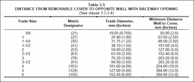
c) A conduit body of 3/4 (21) trade size and larger that permits a change in the direction of the wiring passing through it shall have a distance between each raceway entry and the opposite wall of the body at least six times the trade diameter of the largest raceway that can be connected to it plus the sum of the trade diameters of all other entries in the same wall, except that where a raceway entry is in a wall opposite a removable cover, the distance from that wall to the cover shall be permitted to be no less than that specified in Table 3-5 (Attachment 14).
[NEMA FB1 Sec. 3.3.3.4]
| The thickness of a conduit body cover shall be in accordance with Table 2-4 (Attachment 5). [NEMA FB1 Sec. 3.3.3.6] |
| Marking: A conduit body that is intended for use with a specific combination of conductors shall be permanently marked with the maximum number and maximum size of the conductors for which it is intended. The following conduit bodies need not comply with this requirement: a) A conduit body that will accommodate only 1/2 (16) trade size conduit. b) A conduit body marked for use only with No. 6 AWG or smaller conductors. c) A conduit body complying with 3.3.3.4 (Item B52). [NEMA FB1 Sec. 3.3.3.7.1] |
International Codes & Standards
| 3. NFPA 70 – National Electrical Code, 2008 Edition |
| 4. SAES-P-104 – Wiring methods and Materials, January 2008 |
| 5. SAES-P-100 – Basic Power System Design Criteria, June 2007 |
| 6. UL 514B – UL Standard for Safety for Conduit, Tubing, and Cable Fittings, February 2004 |
| 7. NEMA FB1 – Fitting, Cast Metal Boxes, and Conduit Bodies for Conduit, Electrical Metallic Tubing, and Cable, 2007 |
Table 5-3, Minimum Depth to Integral Bushings – NEMA FB1

Table 2-7, Minimum Wall Thickness at Tapped Holes for Conduit – NEMA FB1
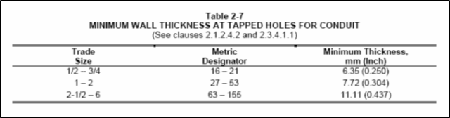
Table 5-6, Maximum Number of Threads in the Wall of a Cast Metal Box Having Through Threaded Entries – NEMA FB1
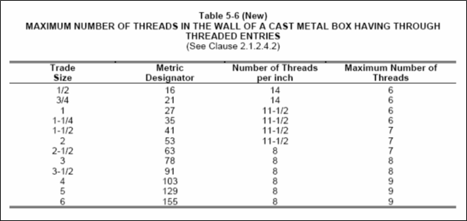
Table 2-2, Inside Diameter of Throats and End Stops for Fittings and Bushings – NEMA FB1
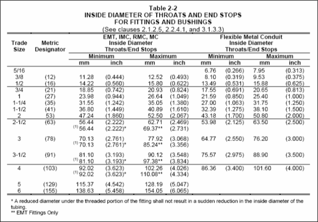
Table 2-4, Wall Thickness of Fittings – NEMA FB1
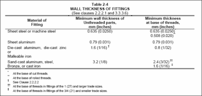
Table 2-5, Metal Thickness – NEMA FB1
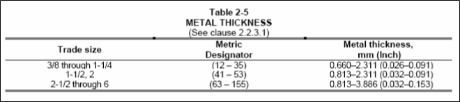
Table 2-6, Minimum Thread Projection of Box Connectors – NEMA FB1
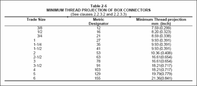
Table 5-7, Compatibility of Knockout Dimensions with Locknuts, Bushings and Metal Conduit (IMC or Rigid) to Assure Coordination – NEMA FB1
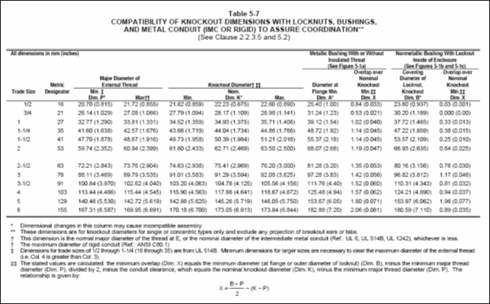
Table 3-2, Radius of Bend of Angle Fittings – NEMA FB1

Table 3-3, Outside Diameter of Flexible Metal Conduit Fitting of the Screw-In Type – NEMA FB1
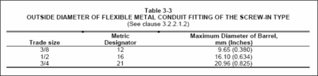
Figure 3-1 & 3-2, Tangential and Type Screw Radial – NEMA FB1
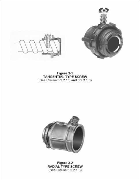
Table 2-1, Standard Assembly Torque Values for Conduit and Cable Fittings – NEMA FB1
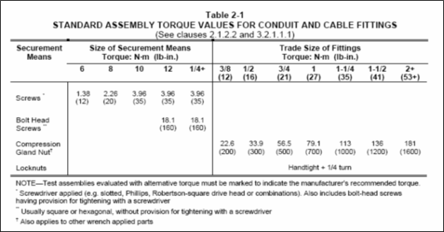
Figure 3-5, Configuration of Single-Gang FS and FD Box Face – NEMA FB1
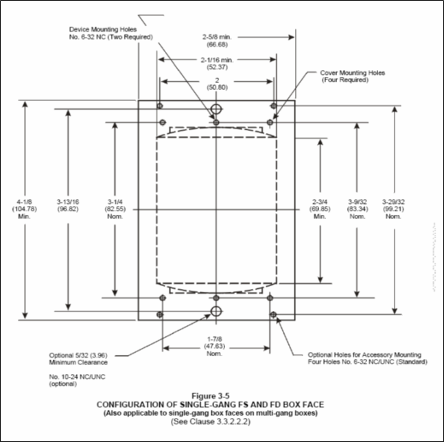
Table 3-5, Distance from Removable Cover to Opposite Wall with Raceway Opening – NEMA FB1