Industry Codes and International standards for Erection of Reciprocating Compressor
- REIE 686 Recommended Practices for Machinery Installation and installation design
- Pl-618 Reciprocating compressor for petroleum chemical & gas industry for Erection of Reciprocating Compressor
Latest Revision of the following Documents shall be used for Erection of Reciprocating Compressor.
- Vendor Drawing
- Foundation Drawing
- Equipment details
Tools and equipment for Erection of Reciprocating Compressor
Tools and equipment needed should be in good condition and must be checked by competent person and respective supervisor prior to use in the plant. Third Party vehicle and equipment inspections and vehicle stickers required. Saudi Aramco certified where required. These Includes but not limited to:
- Calibrated engineering level with calibration certificate
- Corrective wrenches all required range
- Crane
- Certified sling and hoists
- Chipping hammer/bush hammer
- Welding Machine
- Compressor
- Calibrated Alignment and Levelling tools (dial indicator, precision master level, other measuring equipment);
- Final shaft alignment shall be as per Vendor’s recommended method.
- Low-height rampack jacks
- Chain block
- Vendor-supplied tools, if any
- Rubber mallet
Method Statement for Erection of Reciprocating Compressor
Equipment Preservation/Protection:
Vendor’s/Manufacturer’s recommendation for equipment preservation shall be followed.
Equipment Rust Preservation shall be done using applicable vendor/manufacturer’s documents.
When the equipment arrived at site, shop preservation shall be checked. Where necessary damage to preservation shall be rectified without delay.
Preparatory Works:
Secure work permit and other applicable approved documents prior to work commence.
Tools and equipment shall be made operational and available for use. Ensure tools are color-coded accordingly.
Conduct lifting study & get approved lifting plan.
Prior to the arrival of equipment on site, Contractor / Subcontractor shall review the manufacturer’s requirement and the requirements of this specification regarding on site storage of the equipment. These requirements shall be incorporated to site preservation plan and adhere to in all respects.
Install barricades to confine the area for authorized personnel only.
Foundation Preparation:
- Confirm acceptances & turnover of civil works foundation/pedestals with a signed copy of works release notice.
- After receiving foundation release note, the following points shall be checked with the latest relevant drawing.
• Distinct position (centre) marking and height (level) marking on the foundation, It will be referred for alignment work of level and position.
• Size and number of anchor bolt and nuts, position of anchor bolts with projection.
• Existence of damages and rust of threaded of buried anchor bolts with projection.
- Using theodolite establish centerline of the equipment unit. Mark centerline on concrete foundation using paint/ prick punch.
- Trace centerlines of foundation bolt holes with reference to gridlines. Check Verticality/plumbness of anchor bolt.
- Clean the surface thoroughly by blowing with oil-free from air compressor.
Centerlines lost due to chipping operations will retrace a new
- Anchor bolts shall be protected properly to avoid damages during chipping/padding work and keep it up to the equipment installation.
- The elevation of the chipped top foundations shall allow for at least 25mm of grout under the base plate as per SAES-Q-005 Concrete
Foundation. - The bottom of the equipment bases shall be cleaned and free of laitance, oil or grease.
- In case that leveling jack bolts are not provided on the equipment base frame, it shall be perform using straight liners on both side of bolts basically.
- Laitance shall be removed from the surface of the foundation and boxes by chipping to ensure good adherences of padding and grout materials
to the surface preparation.
Padding:
- Pads and liners shall be machined flat parallel and larger than the foot of base frame.
- Pads material shall be in accordance with ASTM A283 Gr. C, D or equivalent.
- Pad shall be hot dip galvanized in accordance with ASTM A123 or coated with zinc rich epoxy primer in APCS-1C of SAES-H-101V as applicable.
- In general, the distance between pads shall not exceed 800mm. If the distance becomes more than 800mm, an additional pad shall be added in
between. - Pad size shall be selected as per the anchor bolt size as follows:
• Bolt diameter M24 or 1 inch and below Pad width 50mm
• Bolt diameter M30-M48 or 1-1/4 to 2 inches Pad width 75mm
• Bolts diameter M56 or 2-1/4 inches and above Pad width 100mm
- Number of pads shall be determined so the load pressure will be less than 30kg/cm2.The supporting load can be calculated as per following formula.
L=W/NxAxB
L: Load supported by liner (kg/cm2)
W: Lifting load of equipment (kg)
N: Number of pads
A: Width of base plate for equipment (cm)
B: Width of liner (cm)
- The length of pad shall be 20 mm to 30 mm longer than the width of the equipment bases.
- The thickness of the both taper and straight liners shall be at least 10 mm and the minimum thickness of the tapered ends shall be 2 mm.
Adjustment allowance shall be 4 to 6 mm. - After finishing padding work, following points shall be checked.
• Position of center and elevation line of foundation
• Elevation and position of pads
• Cleanliness of concrete surface
• Condition of anchor bolts
Setting of Liner
- Prior to the installation of liners and equipment, the liners and grouting portion of foundation shall be chipped and all concrete laitance shall be
removed from portion. - Flat liners shall be installed at the designated position with pads of cement grout at least seven days before equipment installation. ln case non-shrink grout material is used; the curing duration shall be according to the manufacture’s recommendation.
- In case that wedges liners are used the level of padding with a flat liners need to be adjust to meet with the final equipment elevation.
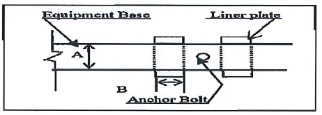
- Equipment supports are provided with stainless steel (AISI Standard Type 300) shims minimum 3mm thickness:
• The maximum shim stack height shall not exceed 12 mm thick
• Only one 3 mm (0.125 in.) or thicker shim per mounting foot is allowed.
• All shims are to straddle hold down bolts and jackscrews.
• Maximum number of shims under any equipment support foot is five - All mounting surfaces that are not to be grouted shall be coated with a rust preventive immediately after machining.
- Mounting plates shall not be drilled for equipment to be mounted by others.
- Anchor bolts shall not be used to fasten drive equipment to the mounting plates.
- Diametrical clearance between anchor bolts and the anchor bolt holes in the mounting plates shall be a minimum of 6 mm (1/4 in.)
Lifting of Reciprocating Compressor
- Prior to the installation work, the foundation shall be checked for the following:
• Location, orientation, elevation and conditions of support foundation conformed with Project plan drawings
• Level of pads on the chipped surface.
• Completely free from foreign material especially on chipped surface and anchor boxes.
• Concrete foundation has reached the curing period up until the compressive strength has reached 70% of the specified strength but not less than 7 days after placement - Prior to the installation work, the equipment shall be checked for the following points.
• Compressor skid, Compressor, Cylinder Heads & other major components are free from any physical damage.
• All components of the system such as relief valves and control valves shall be identified with a permanently affixed corrosion resistant tag showing the component identification number referenced to the piping and instrument diagram.
• Rotation arrows shall be cast in or attached to each major item. - Prepare lifting location were the crane will be located and position.
- Prepare and set all rigging accessories according to arrangement.
- Checked wind condition, lift shall not proceed when wind velocity is greater than required of crane.
- Stabilized ground areas where crane will be located and positioned. Crane mats shall be provided in accordance to findings of soil bearing
pressure. - Crane lift & rigging requirement shall refer to approved document.
- The equipment shall be lifted by lifting lugs, lifting trunnion, tailing lugs or shell not by nozzles.
- Equipments shall be protected by wooden blocks, rubber or other suitable material that will prevent equipment from damages caused by sling wire.
- Install reciprocating compressors on top of the foundation as per approved lifting plan.
- Equipment shall be set and aligned at the proper position, elevation, levelness and perpendicularity in accordance’s with the drawing.
Centering of Compressor:
- Leveling of Crankcase Assembly Parts.
- Confirmation of the fitting elevation of the parts
- Level confirmation of crankcase.
-
- Measuring places shall be:
- Machine finished surface of crankcase.
- Flange surface of cylinder top
- Sliding surface of cross guide
- Measure with precision level, thickness gauge, straight edge, etc.
- Confirm the setting position with bob weight on the basis of black line of axial and cylinder centerline on foundation.
- Measuring time shall be done before and after grouting.
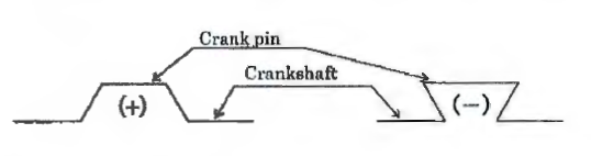
Measurement of Crankshaft Deflection
• Deflection of crankshaft is measured to confirm that crankshaft is installed normally and that no abnormal force is applied to the crankshaft.
• Fit the deflection gauge, which is supplied by MES, between the webs of crankshaft, read the graduation of dial gauge.
• Measure when the crank pin is at point T, B, Rand L-4. However, when it is measured at connecting rod , it will be touched the deflection gauge at certain rotating angle (drawings are shown below) so that it is measured at 4 places.

In taking the measured record, the indication (+) and (-) of crankshaft deflection is marked as follows:
Normally deflection gauge is fitted at one half of journal diameter, but the cap of connecting rod will be touch the gauge at the time of measurement so it is
fitted a little outside of regular measuring place for actual measurement. The measured value therefore is corrected by the following formula. Deflection
value equals value measured by regular deflection gauge x A/8.
In this case,
A is (270+325)/2 =297.5mm *1),
B is distance between crank pin center and deflection gauge center. The dimension of “B” shall be measured between the horizontal split surface
of big-end of con-rod and deflection gauge with convex rule. *1 ):
A=(Piston stroke + Crankshaft diameter)/2.
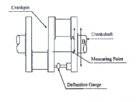
• Standard value of deflection at the time of installation shall be within:
• 1 / 1000 x piston stroke; 0.027mm Refer to Compressor Technical Data
• Measuring time for crankshaft deflection shall be:
0 Leveling of crankcase (before anchor bolt grouting).
0 After grouting (after anchor bolts tightening).
0 After connection with driving machine.
• Turning is conducted by temporary turning bar and turning driver. Before turning, supply oil to each bearing, crosshead guide and main motor. Especially in case of long-term storage, it is essential for the above parts to supply.
Measurement of Clearance between Crosshead Guide and Crosshead
• Measure clearance of rubbing surface of crosshead guide and crosshead. Confirm · that crosshead rubs rubbing surface of crosshead guide with a fixed clearance.
• Measure clearance of the following spots with thickness gauge.
0 Measure clearance at spot F and A on cylinder side (CT) and F, A on crank case side (CB) at top position of piston.
0 Measure clearance at spot F, A on cylinder side (CT) and F, A on crank case side (CB) at bottom position of piston.

Measurement of Piston Rod Run Out.
• Before and after grouting, measure piston rod movement to upward and downward, and to left and right at top dead point and bottom dead point of piston.
• Depending on result of the measurement, confirm level of crosshead guide and cylinder installed.
• Measuring Method
Fit deal gauge on bottom of piston rod outside circumference on compartment chamber and on side (opposite motor side).
Set dial gauge to O (Zero) at bottom dead point of piston, read dial at top dead point of piston; and take its record .
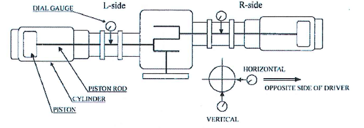
- Keep run-out of both up-ward-downward and horizontal direction within 0.10mm.
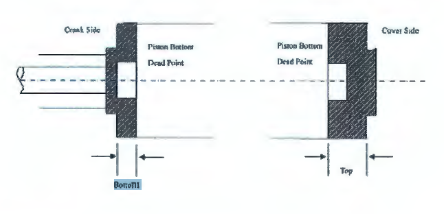
• Measurement of Piston Top Bottom Clearance - Measurement clearance between piston and cylinder cover at top dead point and bottom dead point of piston.
- Remove each discharge valve cover end and at cylinder bottom cover end.
Measure clearance from discharge valve hole. While turning of crankshaft, put lead wire into space between piston and cylinder cover so that lead wire can
so pressed by piston at top and dead points. - Measure thickness of lead wire with micrometer.
Refer to Installation Record for standard criteria of clearance. The clearance is adjusted when assembled in shop.
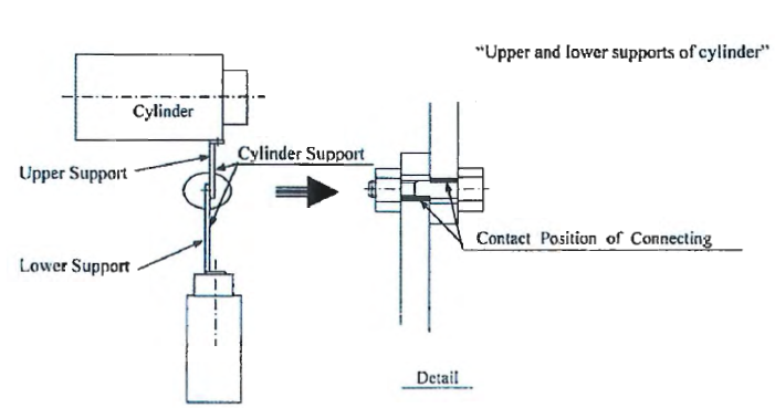
Setting of Cylinder Support
• Installation of Upper Support on cylinder
0 Rigidly fasten bolts between cylinder and upper support.
• Installation of Lower Support
0 Install lower support to upper support with connection bolts for these supports as shown in refer to chart below. “Upper and lower supports for cylinder”.
0 Lift lower support until connection bolts touch to upper side of bolt holes of upper support. At this time, the bolt hole between upper and lower support becomes as shown in refer to chart below. “Upper and lower supports for cylinder”.
0 Fasten connection bolt between upper and lower support with torque wrench.
• Fitting and Grouting of Foundation Bolts.
- Mount foundation bolts to lower support
- Carry out grouting for foundation bolts.
- Adjustment of Cylinder Support.
- After curing of the foundation bolts, set up small jack (W 5/8″) and flat liner on side of the foundation bolts for leveling. Small jacks and flat liners are furnished by MES.
- Adjust level of cylinder with small jack. Carry out grouting for lower support of cylinder.
Grouting
- Non-Shrink Grout. Following items shall be consider before grouting execution:
- Prior to grouting, concrete repair have been performed in accordance with SAIC-Q-1062 as based on SAER-5803.
- Grout shall be mixed as per the Grout Manufacturer’s instructions.
- Foundation preparation shall be in accordance with the grout manufacturers written instruction.
• Concrete foundations shall be cured for a minimum of 7 days before surface preparations for grouting.
• Laitance, oil-soaked or damaged concrete shall be removed down to sound concrete by chipping to the level of sound fractured aggregate or to a minimum of the top 1 inch (25mm) of the concrete.
• All dust and loose particles shall be removed with clean, dry, oil free compressed air.
• Grout Formwork, where required, shall be constructed with adequate strength, rigidity and required dimensions to permit grout placement and avoid leakage.
• A bond breaker shall be applied to the formwork that will be in contact with the grout.
• After cleaning, the foundation shall be protected with 0.15mm polyethylene sheeting to prevent contamination.
• Concrete surfaces in contact with the grout shall be saturated with clean water before grout placement. The surface shall be damp but free from standing water.
• Joints in the grout shall be located as shown in the drawings or as recommended by the manufacturer.
• Grout shall be placed in only one direction to prevent trapping air; Grouting shall be quick and continuous to avoid segregation, bleeding or premature initial set.
• Re-tempering of grout by adding water after stiffening is not permitted.
• If the grout is placed through grout holes, it shall be placed from one hole continuously until the grout has passed a second hole. A liquid head pressure shall be maintained at the first access hole until a head pressure is established at the second hole and continued in a similar fashion until the next hole.
• Grout shall be mixed, placed and cured in accordance with manufacturer’s written requirements. The contractor shall read, understand and comply with the manufacturer’s instructions as printed on each unit.
• The grout shall be cut back to the lower edge of the base plate by 45° angle unless otherwise indicated.
Epoxy Grout for Machinery Support.
Following items shall be consider before grouting execution:
- Laitance and oil-soaked or damaged concrete are removed with chipping hammer to sound fractured aggregate, or to a minimum of the top 1 inch (25 mm) of concrete.
- Concrete chipping and removal shall not be performed with heavy tools such as jackhammers as they could damage the structural integrity of the foundations.
- The minimum grout thickness under any portion of the base plate/soleplate shall be 25mm Concrete in contact with the epoxy grout shall be clean, dry and
oil free. - Formworks for epoxy grout are constructed to be liquid tight with adequate strength, rigidity and dimensions to permit epoxy grout placement.
- Form joints and interface between forms and concrete foundation are sealed with grout manufacturer’s recommended sealant.
- Maximum depth of pour and length to width ratio shall be as per manufacture’s recommendations.
- Elevation of the formworks shall be check to ensure that the top surface of the grout will match the elevation shown on the construction drawings.
- Three coats of paste wax shall be applied to the inside surface of forms or other manufacturer recommended procedure for preventing bonding of the epoxy grout to the formwork.
- Suitable shelter or enclosures shall be provided to protect the foundation and base plate from direct sunlight, dew, rain or other inclement weather. During cold weather, adequate enclosure and heating shall be provided to maintain foundation and base plate temperature with acceptable range specified by the grout
manufacturer. - Expansion joints in epoxy grout shall be spaced at a maximum of 48 inches (1.4 m) unless otherwise specified in the contract documents.
- Expansion joints shall be made from closed-cell neoprene or polyethylene foam board, having a minimum thickness of 1 inch (25 mm) unless otherwise noted in the contract documents.
- Expansion joints shall be fixed into position to prevent movement and shall be sealed at formwork and at the concrete base to prevent epoxy grout from passing around or underneath the joint during placement.
• All mounting plate/soleplate outside corners shall have a minimum of 50mm radius to prevent cracking of the foundation grout due to stress concentration at the corners.
• Baseplate leveling jack screws shall be provided with stainless steel leveling pads.
• Mounting plate jackscrews shall be liberally coated with paste wax or grease to prevent grout adherence.
• Mounting plate jackscrews shall be liberally coated with paste wax or grease to prevent grout adherence.
• Suitable shelter or enclosures shall be provided to protect the grouted foundations from direct sunlight and weather.
• Foundation and base plate temperature are within the acceptable range specified by the grout manufacturer until the grout has cured.
After grouting works following items shall consider:
• The grout shall be checked for voids after the grout has cured. Any voids shall be filled according to epoxy grout manufacturer’s recommendations.
• After the void grout has cured, the base plate shall be recheck to ensure that all voids are filled with grout. Any voids still exist shall be rectified.
• Exposed expansion joints shall be sealed with the epoxy grout manufacturer’s recommended sealant.
The final level of the epoxy grout is flush with the top horizontal chamfer edges built into the formwork.
1st Alignment of Main Motor
Lifting of Main Motor
• The main motor shall be lifted horizontally and set carefully on the foundation using crane and wire rope that have enough strength. On the lifting of motor, take care that crankcase and other equipments are not damaged in these jobs.
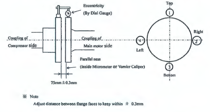
Temporary Alignment Procedure between Driver and Compressor.
• Tools for temporary of alignment.
• For measurement of eccentricity of coupling use dial indicator with magnet base or mechanical attachment.
For measurement of parallelness of coupling, use inside micrometer or dial gauge with magnet base.
Measurement of eccentricity of coupling.
• Surface of the setting position of dial indicator and measuring surface of the dial indicator shall be cleaned.
• To measure at four points (top, bottom, right and left) which divide the circumference of coupling equally and are marked temporarily as 1,2, 3, and 4.
• Dial indicator shall be set.
• Eccentricity shall be measured at four points by turning the crankshaft.
Measurement of parallelness of coupling.
• Parallelness of coupling shall be measured by measuring the gap between coupling clearance at four points (top, bottom, right and left) that are marked. Prior to, measuring the parallel ness, it is important that the gap between couplings should be adjusted to obtain the correct magnet center position of main motor.
• Level of driver unit shall be confirmed at the same time.
0 Level of driver unit shall be measured at the machined surface of base plate of motor by using the sprit level.
0 Level shall be confirmed in parallel direction and right angle direction of shaft.
• Temporary alignment of main motor shall be confirmed before setting anchor bolts.
0 Temporary alignment shall be done according to tolerance at final alignment.
0 Tolerance at final alignment.
o Eccentricity of coupling is within 10/100 mm.
0 Parallel ness of coupling is within 5/100 mm.
0 Leveling of driver unit is within 30/100 mm.
0 The dropping value of crankshaft coupling by putting flywheel should be considered.
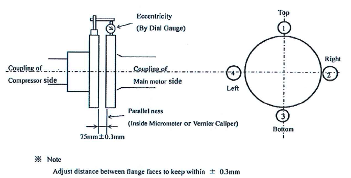
• In connecting the main motor with compressor, confirm that the magnet center and air clearance of the main motor are within tolerance. Adjustment of the motor is made in accordance with operating manual.
2nd and Final Alignment of Main Motor
• Procedure of 2nd and final alignment shall be done according to the “Temporary Setting and 1st Alignment of Main Motor “by tightening the anchor bolts and jacking up the motor with small jackscrews.
• Tolerance at 2nd and Final Alignment
0 Eccentricity of coupling within 101100mm
0 Parallelness of coupling within 5/100mm
• After 2nd alignment, motor base plate shall be grouted.
• After confirming the final alignment and connecting the coupling of main motor and compressor deflection of crankshaft shall be confirmed within standard value. Standard clearance shall be referred to “Installation Record”.
Setting of Flywheel
• Preparation for Flywheel Setting
° Cleaning of the setting surface of flywheel on crankshaft coupling, main motor coupling, and the bolt holes.
° Cleaning of flywheel surface (both sides) and the bolt holes.
0 Before sliding of main motor, confirm the electrical personnel to protect for main motor is necessary or not. If necessary, appropriate electrical protection to be carried out.
0 Remove LO in plugs of bearing housing, and fill in LO with appropriate quantity.
0 Make match marks for relative position (at four corners of main motor) between main motor and sole plate by using center punch and steel compass. So it is easy to install the main motor at regular position for restoration.
0 Set the dial gauges at main motor front and rear, left and right side (total 4 points) on the main motor base plate.)
0 Remove all of shims between main motor and sole plate to avoid the damage during motor sliding work. Make clear identification for mounting positions of shims before removing.
0 Slide main motor around 25mm to anti coupling side, which is relative amount between end plate of main motor and crankshaft coupling to set the flywheel.
° Fix main motor with jack-bolts in front and rear, and left and right corner not to move main motor.
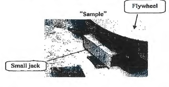
• Setting of Flywheel.
Set the dial gauges to crankshaft coupling, horizontal and vertical, to confirm the drop and horizontal moving amount of crankshaft for flywheel weight after setting.
Hang the flywheel vertically and fit to crankshaft coupling.
With two bolts, tighten up flywheel to crankshaft coupling.
Loosen the flywheel lifting wire.
Confirm the drop and horizontal moving amount of crankshaft coupling by fitting flywheel weight.
0 Lift up the flywheel again to return the vertical and horizontal amount of dial gauges “zero” position. Refer to attached sample picture.
• Connecting of Flywheel and Main Motor Coupling.
0 Restore main motor on regular position sliding on base plate and insert shims removing before main motor sliding. Confirm the regular position by the match marks and the dial gauges setting before main motor sliding.
Confirm the magnet center of main motor.
0 When the main motor position and magnet center are acceptable, tighten the coupling bolts with hydraulic oil pressure. Oil pressure is noted on the attached tightening torque list. Order of tightening coupling bolts in indicated in next sketch.

0 After tightening bolts with hydraulic pressure, tighten the lock nuts of coupling bolts.
0 After tightening lock nuts, measure deflection of crankshaft. Measure upper clearance of guide bearing and main bearing with thickness gauge, and confirm any no irregular contact.
0 If fine adjustment is necessary, carry out the adjustment again with measurement of crankshaft deflection by moving main motor position and shim combination.
°ଶ Fit flywheel cover.
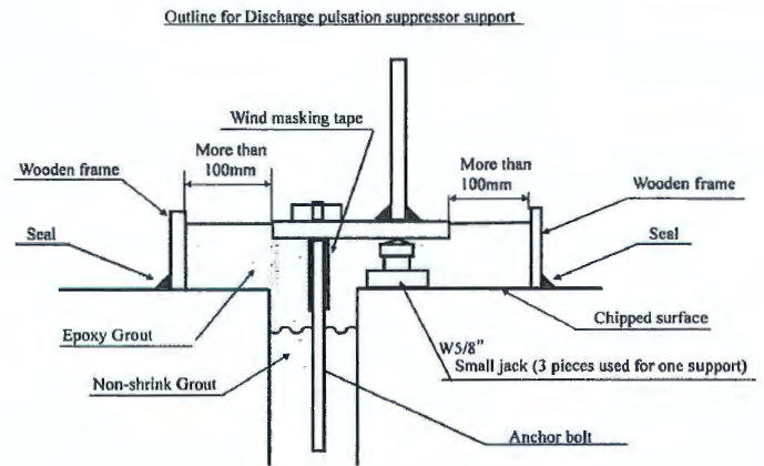
• Setting of Pulsation suppressor.
°ଶ Fitting of discharge pulsation suppressor.
0 Before fitting of the discharge pulsation suppressor, clean the connecting flange.
0 Measure the clearance of surface between the connection flange and cylinder flange and adjust it so that the error is within 0.1 mm.
0 Tighten the cylinder flange and discharge pulsation suppressor through packing uniformly with tightening bolt.
°ଶ Fit the support for discharge pulsation suppressor under the pulsation suppressor through adjusting liner. Suspend the foundation bolt on the support.
0 Stay for the support is set between the foundation and the support, using small jack provided by MES.
°ଶ For grouting of support, a wooden frame is made on the foundation.
• Fitting of the suction pulsation suppressor.
°ଶ Clean the packing seat of connecting flange and the cylinder.
0 Hang up the pulsation suppressor horizontally.
°ଶ Confirm the fitting direction of the pulsation suppressor with general arrangement drawing.
0 Slowly bring the pulsation suppressor to cylinder connecting part.
0 Slightly tighten the flange on the cylinder and pulsation suppressor through packing.
°ଶ Fit the support for suction pulsation suppressor under the pulsation suppressor through adjusting liner. Suspend the foundation bolt on the support.
a. Measure the clearance between the flange of the pulsation suppressor and the cylinder in longitudinal and vertical direction of the pulsation suppressor at four places and adjust the clearance so that the difference in within 0.1 mm, using small jack provided by MES.
0 Uniformly tighten the flange tightening bolts for the pulsation suppressor with the bolt.
0 Bury the foundation bolt in the ground with non-shrink Grouting material.
0 After the curing of grout, tighten the foundation bolt.
0 Grout the discharge pulsation suppressor support with non-shrink grout.
0 Tighten the foundation bolt after the curing of grout and remove the wooden frame.
0 After tightening the foundation bolt, slack the tightening bolt of adjusting liner between the support and pulsation suppressor and confirm that there is no clearance. Tighten the bolt for tightening of the pulsation suppressor once again.