An excitation system is an integral part of many electrical generators, particularly in power plants, and it plays a crucial role in controlling and maintaining the generator’s output voltage. The primary function of an excitation system is to provide a controlled direct current (DC) voltage to the generator’s rotor windings, creating a magnetic field within the rotor. This magnetic field induces an alternating current (AC) voltage in the generator’s stator windings, which is then sent to the electrical grid.
What is Excitation System?
Excitation systems are critical for maintaining voltage stability in power systems. They ensure that generators can provide consistent and reliable electrical power, and they play a vital role in grid control and load balancing. Modern excitation systems often use advanced control algorithms and digital technology to provide precise voltage regulation and respond rapidly to changing grid conditions.
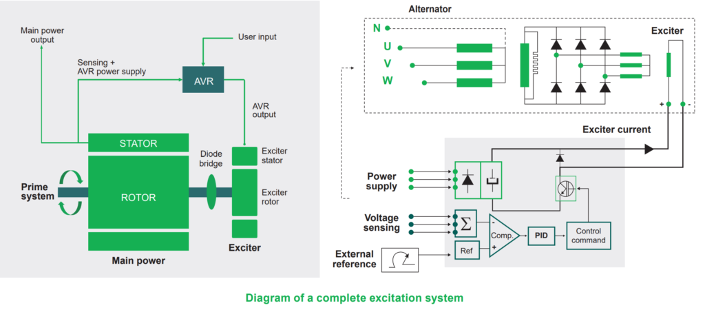
Complete Excitation System Diagram
Functions and Performance Requirements
The excitation system serves two primary functions:
1. Providing Direct Current to the Synchronous Generator Field Winding:
- The excitation system supplies direct current (DC) to the field winding of the synchronous generator. This DC current creates a magnetic field within the generator’s rotor, which is essential for generating electrical power.
2. Performing Control and Protective Functions:
- The excitation system is responsible for executing various control and protective functions crucial for ensuring the reliable and safe operation of the power system.
The performance requirements of the excitation system are determined by the following factors:
a) Generator Considerations:
- Supply and Adjust Field Current: The excitation system must supply and adjust the field current to the generator as the generator’s electrical output varies within its continuous capability. This ensures that the generator can produce the required electrical power while maintaining stable operation.
- Response to Transient Disturbances: The excitation system should respond to transient disturbances by applying appropriate field forcing to address issues related to the generator’s short-term capabilities. These disturbances may include:
- Rotor Insulation Failure: High field voltage can lead to rotor insulation failure, so the excitation system must prevent excessive field voltage.
- Rotor Heating: Excessive field current can cause rotor heating, and the excitation system should avoid this condition.
- Stator Heating: High VAR (volt-ampere reactive) loading can lead to stator heating, so the excitation system needs to manage VARs effectively.
- Excess Flux (Volts/Hz): Keeping the flux within acceptable limits concerning voltage and frequency (volts/Hz) is crucial to prevent overheating and damage.
b) Power System Considerations:
- Contribute to Voltage Control: The excitation system plays a role in controlling system voltage, ensuring it remains within acceptable limits. This is essential for maintaining the stability and reliability of the overall power system.
- Enhance System Stability: The excitation system contributes to the effective control of the power system, which helps enhance system stability. It ensures that the generator responds appropriately to variations in load and grid conditions, helping to maintain a reliable power supply.
The excitation system not only provides the necessary DC current to the generator field winding but also performs critical control and protective functions. These functions are essential for maintaining generator performance within its capabilities, responding to transient disturbances, controlling system voltage, and improving overall power system stability.
Excitation System Components / Elements:
The components and functions of an excitation system can be summarized as follows, with explanations of their roles in ensuring stable and safe generator operation:

- Exciter:
- Function: The exciter provides a direct current (DC) power supply to the generator’s field winding.
- The exciter’s primary role is to generate and deliver the necessary DC current to the field winding of the generator. This DC current establishes the magnetic field required for power generation.
- Regulator:
- Function: The regulator processes and amplifies input control signals to a level and form suitable for controlling the exciter.
- The regulator acts as an intermediary between the control signals and the exciter. It takes input signals and adjusts them to precisely control the exciter, ensuring that the generator operates at the desired voltage and frequency levels.
- Terminal Voltage Transducer and Load Compensator:
- Function: These components sense the generator’s terminal voltage, rectify and filter it to convert it into a DC quantity, and then compare it with a reference voltage. Load compensation may be included to maintain voltage at a remote point.
- These components monitor the generator’s terminal voltage and make adjustments as necessary to maintain it at the desired level. Load compensation helps ensure that voltage remains consistent, even when subjected to varying loads.
- Power System Stabilizer:
- Function: The power system stabilizer provides an additional input signal to the regulator to dampen power system oscillations.
- Power system stabilizers help enhance the stability of the overall power system. By providing supplementary input signals to the regulator, they assist in counteracting power system oscillations, ensuring smoother and more stable generator operation.
- Limiters and Protective Circuits:
- Function: These components are responsible for preventing the exciter and generator from exceeding their capability limits.
- Limiters and protective circuits serve as safeguards to prevent the exciter and generator from operating beyond their designed capacity. They play a critical role in protecting the equipment from damage and ensuring safe and reliable operation.
An excitation system comprises various components with specific functions. These components work together to provide the necessary DC power to the generator’s field winding, regulate voltage and frequency, stabilize the power system, and safeguard against equipment overload or damage. This coordinated operation ensures the efficient and secure generation of electrical power.
Excitation System Types:
Excitation systems can be categorized into three main groups based on their power sources:
1. DC Excitation Systems:
DC excitation systems derive their power from a direct current source. They supply this DC power to the generator’s field winding, creating the necessary magnetic field for power generation. DC excitation systems are known for their reliability and precise control over the generator’s output.
2. AC Excitation Systems:
AC excitation systems, on the other hand, utilize an alternating current source to generate the required magnetic field in the generator. While less common than DC systems, AC excitation systems are still employed in certain applications and offer their own set of advantages.
3. Static Excitation Systems:
Static excitation systems represent a modern approach to generator excitation. They use semiconductor-based electronics to control and regulate the excitation current. These systems are known for their high precision and adaptability, making them suitable for various generator types and operating conditions.
These three categories represent the different approaches to providing excitation power to generators, each with its own characteristics and advantages. The choice of excitation system depends on factors such as generator type, application, and desired control capabilities.
DC Excitation Systems:
DC excitation systems are characterized by their use of direct current (DC) generators as a power source for providing excitation to generators. These systems have specific features and a historical context:
- Power Source:
- DC excitation systems typically employ DC generators as their power source. These generators can be driven by a separate motor or directly by the shaft of the main generator.
- Excitation Types:
- DC excitation systems can be classified into two main types:
- Self-Excited: In self-excited systems, the DC generator is capable of generating its own excitation power. This means that it can provide the necessary DC current to the generator’s field winding without external assistance.
- Separately Excited: Separately excited systems, on the other hand, rely on an external power source to energize the DC generator, which, in turn, provides excitation to the main generator.
- Historical Significance:
- DC excitation systems were prominent in the early-to-mid 20th century, particularly from the 1920s to the 1960s. During this period, they were widely used for controlling and regulating generator excitation.
- Challenges and Transition:
- One of the significant limitations of DC excitation systems was their relatively large size. As technology advanced and more compact alternatives became available, DC systems lost favor in the mid-1960s. They were gradually superseded by more compact and efficient AC excitation systems.
- Voltage Regulation:
- Voltage regulation in early DC excitation systems often involved non-continuous rheostatic methods, which used resistors to control the field current. Later systems transitioned to more advanced techniques, such as magnetic rotating amplifiers, to achieve better and more precise voltage regulation.
DC excitation systems were once a dominant technology for controlling generator excitation. However, their large size and limited capabilities led to their decline in favor of more compact and efficient AC excitation systems, which offered improved voltage regulation and control.
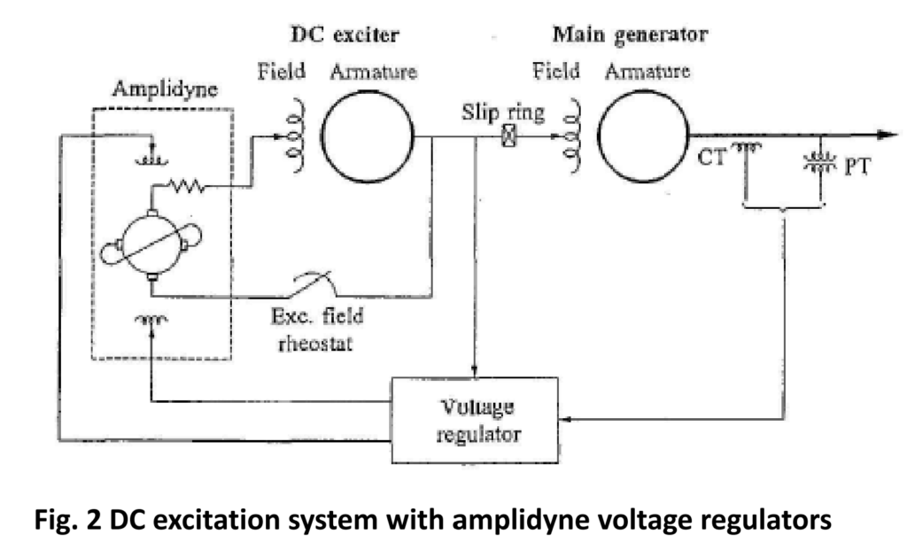
An amplidyne is an electromechanical device designed for amplifying signals in various industrial applications. Its fundamental components include:
- Electric Motor and DC Generator:
- An amplidyne comprises an electric motor that drives a DC generator.
- Signal Input and Output:
- The signal requiring amplification is applied to the generator’s field winding. As a result, the generator produces an amplified output voltage, which is essentially an amplified version of the input field current.
- Industrial Use:
- Amplidynes find their primary utility in industrial settings, particularly in high-power servo and control systems. These devices excel at amplifying low-power control signals, making them crucial for precision control in various applications.
- Obsolescence:
- Although amplidynes once played a significant role in industrial control systems, they have become largely obsolete in modern times. Advancements in electronic amplification technologies have rendered them less common.
In essence, an amplidyne is an electromechanical amplifier that leverages the relationship between an electric motor and a DC generator to amplify control signals in high-power industrial applications. However, due to advancements in electronic amplification methods, the use of amplidynes has diminished, and they are no longer prevalent in contemporary industrial systems.
Figure 2 illustrates a simplified schematic of a standard DC excitation system featuring an amplidyne voltage regulator. Here’s a breakdown of the key components and their functions:
- Self-Excited DC Exciter: This component serves as the primary power source for the excitation system. It supplies current to the field winding of the main generator through slip rings. The self-excited exciter is capable of generating its own field, enabling it to operate independently.
- Amplidyne Voltage Regulator: The exciter’s field current is controlled by an amplidyne voltage regulator. This regulator is responsible for making precise incremental adjustments to the field current. It operates on a buck-boost principle, allowing it to either increase or decrease the field strength as needed to regulate the generator’s output voltage.
- Self-Excitation of Exciter: The exciter is designed to be self-excited, which means that it can generate the necessary field for its operation. This self-excited output not only powers its own field but also contributes to the field strength of the main generator.
In this configuration, the amplidyne voltage regulator plays a crucial role in maintaining the desired output voltage of the generator by finely controlling the exciter’s field current. This buck-boost scheme ensures precise adjustments to the field strength, which, in turn, regulates the generator’s electrical output.
This excitation system design, which includes an amplidyne voltage regulator, offers a high level of control and stability for DC generators. It allows for real-time adjustments to the generator’s field, ensuring that the electrical output remains within the desired parameters.
AC Excitation System:
AC Excitation System: AC excitation systems are designed with the following characteristics:
- AC Power Source: They utilize AC machines, often alternators, as the primary source of power for the excitation system.
- Shaft Connection: Typically, the exciter is mechanically connected to the same shaft as the turbine-generator, allowing it to derive power from the rotating machinery.
- Rectification: The AC output generated by the exciter is rectified to convert it into DC voltage. This rectification process can be achieved through either controlled or non-controlled rectifiers.
- Rectifier Types: Rectifiers in AC excitation systems can take the form of stationary or rotating components, depending on the system’s design and requirements.
- Voltage Regulation: Early AC excitation systems often employed a combination of magnetic and rotating amplifiers as regulators. However, modern AC excitation systems predominantly utilize electronic amplifier regulators for voltage control.
In summary, AC excitation systems differ from DC excitation systems by using AC machines as their power source and rectifying the AC output to produce DC voltage for generator field excitation. These systems have evolved over time, with contemporary designs relying on electronic amplifier regulators for precise voltage regulation.
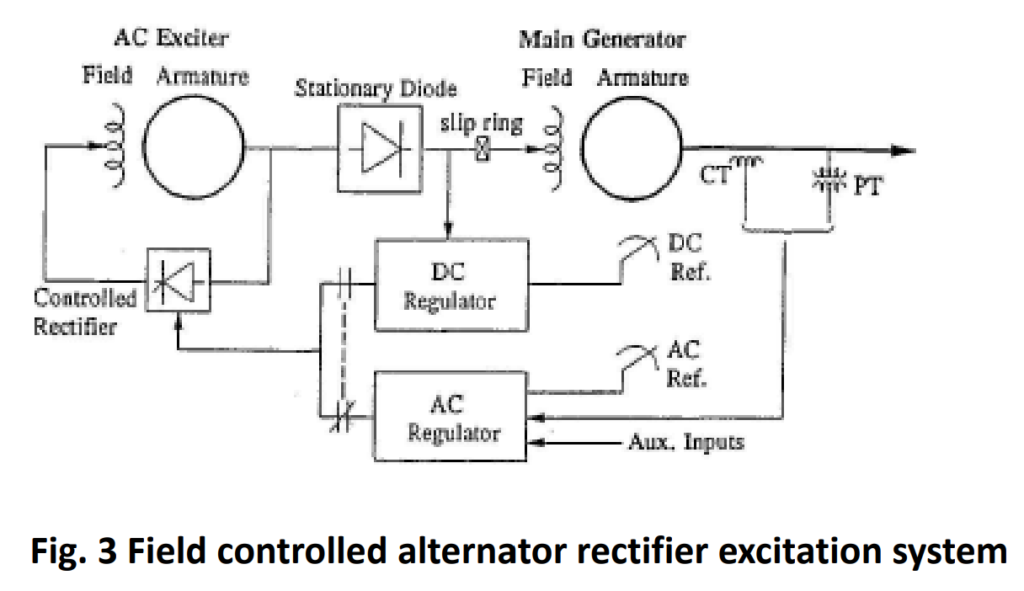
In AC Excitation systems employing non-controlled rectifiers, the regulator is responsible for controlling the field of the AC exciter, which then provides DC output to the main generator field through slip rings.

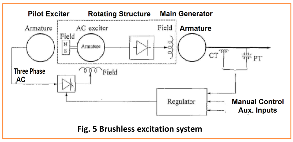
Rotating Excitation System
Rotating Excitation System, often referred to as brushless excitation systems, were designed to eliminate the need for slip rings and brushes. These systems were developed to address concerns related to the use of brushes in supplying high field currents to large generators. However, it’s important to note that brushless excitation systems do not provide direct measurements of generator field current or voltage.
Static Excitation System:
- Static excitation systems consist of stationary components.
- They supply direct current (DC) to the field of the main generator through slip rings.
- The power supply for the rectifiers in these systems comes from the main generator or the station’s auxiliary bus.
- Unlike rotating systems, static excitation systems do not have moving parts like brushes or slip rings.
- These systems are known for their reliability and ease of maintenance.
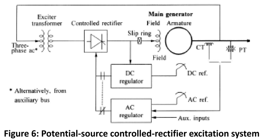
Potential source for controlled rectifier
Following explanation of a potential source for a controlled rectifier in a static excitation system, along with an explanation:
- Potential Source for Controlled Rectifier: In some static excitation systems, the excitation power is sourced from the main generator terminals via a transformer.
- Controlled Rectifier Regulation: This power supply is regulated by a controlled rectifier, a device that converts alternating current (AC) to direct current (DC) with precise control.
- Common Terminology: This configuration is commonly referred to as a “bus-fed” or “transformer-fed” static excitation system.
- Fast Response: One advantage of this setup is its very small inherent time constant, meaning it can respond rapidly to changes in system conditions.
- Voltage Ceiling: It’s important to note that the maximum exciter output voltage in this system is dependent on the input AC voltage. During system faults or abnormal conditions, the available ceiling voltage may be reduced to ensure the system’s stability and safety.
This configuration provides a reliable and responsive means of regulating excitation power in static excitation systems, particularly in the context of generator control and stability.
Compound-source rectifier system
Following explanation of a compound-source rectifier system, along with an explanation:
- Compound-Source Rectifier System: In a compound-source rectifier system, the power supplied to the exciter is generated by utilizing both the current and voltage characteristics of the main generator.
- Achieving Compound Source: This is achieved through the use of two critical components: a Power Potential Transformer (PPT) and a Saturable Current Transformer (SCT).
- Regulation Through Saturation: The system’s regulator plays a pivotal role in controlling the exciter’s output by controlling the saturation of the excitation transformer. By precisely adjusting the level of saturation, the regulator can finely tune the excitation power provided to the main generator.
- Enhanced Field Forcing Capability: Importantly, during a system fault scenario where the generator voltage is significantly reduced, the current input to the system enables the exciter to provide a high field forcing capability. This means that even under adverse conditions, the system can boost the generator’s field current to help stabilize the power system.

The compound-source rectifier system is a sophisticated arrangement that optimizes the utilization of both current and voltage from the main generator to ensure precise control and enhanced performance, especially during challenging situations like system faults.
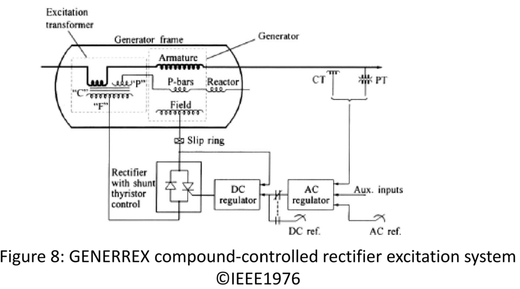
Compound-controlled rectifier system:
In a compound-controlled rectifier system:
- Utilization of Controlled Rectifiers: This system employs controlled rectifiers in the output circuits of the exciter.
- Combining Voltage and Current: It combines both the voltage and current within the generator stator to achieve a specific outcome.
- High Initial Response: As a result of this combination, the system exhibits a high initial response characteristic. It can rapidly and effectively respond to changes in the generator’s voltage and current requirements.
- Full “Fault-On” Forcing Capability: Furthermore, this system possesses the capability for full “fault-on” forcing. In situations where system faults occur, the system can quickly and efficiently provide the necessary excitation to maintain stability and reliability.
The compound-controlled rectifier system is designed to deliver a high level of responsiveness and robustness, making it particularly suitable for scenarios where immediate response and fault tolerance are essential.
Control, Limiting, and Protective Functions in Modern Excitation Control Systems:
A modern excitation control system is a sophisticated and multifunctional component that goes beyond simple voltage regulation. It encompasses a range of control, limiting, and protective functions, all working together to meet specific performance requirements. Figure 9 illustrates the interconnected nature of these functions within the system.
Key points regarding control, limiting, and protective functions:
- Variability in Functionality: The inclusion of these functions within an excitation control system can vary depending on the application and the type of exciter being used. Not all functions may be present in every system.
- Control Functions: Control functions are responsible for regulating specific quantities, ensuring they remain at the desired levels. These functions play a critical role in maintaining stable and efficient generator operation.
- Limiting Functions: Limiting functions are designed to prevent certain quantities from exceeding predefined limits. They act as safeguards to protect the generator and associated equipment from potential harm due to excessive values.
- Protective Functions: In cases where any of the limiting functions fail or if other critical issues arise, protective functions come into play. They are responsible for taking appropriate actions, such as removing specific components or taking the unit out of service, to prevent further damage or hazards.
AC Regulator:
- Primary Function: The AC regulator’s primary role is to maintain the generator stator voltage at the desired level. It ensures that the generator’s electrical output remains stable and within acceptable parameters.
- Integration with Auxiliaries: Additionally, the AC regulator interacts with various auxiliary components within the system to facilitate its control and monitoring functions.
DC Regulator:
- Voltage Control: The DC regulator is responsible for maintaining a constant voltage in the generator field. This manual control is particularly useful during testing, startup procedures, or when the AC regulator experiences faults.
Modern excitation control systems are integral to the efficient and reliable operation of generators and play a crucial role in ensuring stable power generation while safeguarding the equipment from adverse conditions.
Modeling as per IEEE:
The IEEE Recommended Practice for Excitation System Models for Power System Stability Studies provides guidelines and standards for modeling excitation systems in power system stability studies. This recommended practice is essential for power system engineers and researchers who simulate and analyze the dynamic behavior of power systems to ensure their stability under various operating conditions and disturbances.