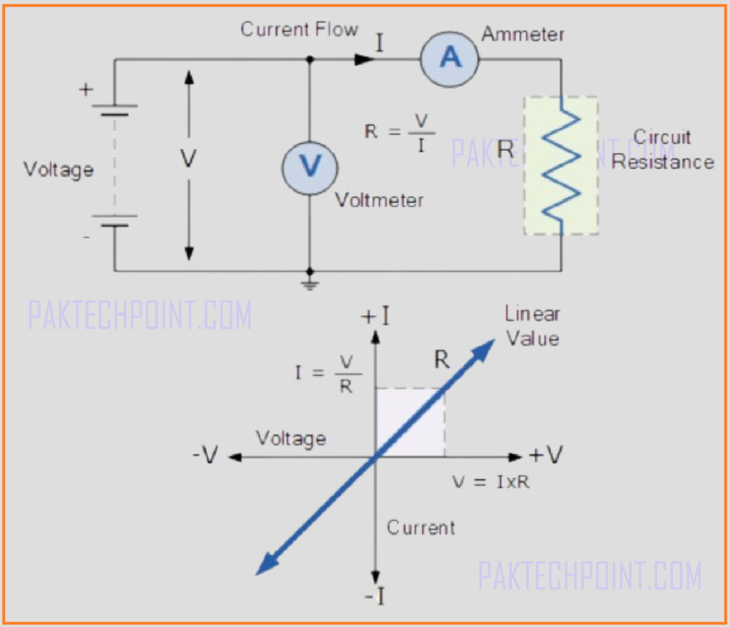
Ohm’s Law states that the current through a conductor between two points is directly proportional to the voltage across the two points. It’s basic relationship between voltage, current and resistance in circuit.
Basic DC circuit theory explains how an electric circuit is made up of interconnected electrical elements. Electrical current, measured in amperes (A), flows through a closed circuit due to a potential difference (electromotive force), known as voltage, measured in volts (V).
All materials are made of atoms, which consist of protons, neutrons, and electrons. Protons have a positive charge, neutrons have no charge (they are neutral), and electrons have a negative charge. Atoms are held together by strong forces of attraction between the nucleus and the electrons.
When protons, neutrons, and electrons are within the atom, they are stable. However, if they are separated, they want to come back together, creating a force of attraction called a potential difference.
In a closed circuit, loose electrons will move towards protons due to this attraction, creating a flow of electrons called electrical current. The material through which electrons move creates a restriction to their flow, called resistance.
Therefore, all basic electrical or electronic circuits involve three key electrical quantities: Voltage (V), Current (I), and Resistance (Ω).
What is Electrical Voltage?
In DC circuit theory, voltage (V) is the potential energy of an electrical supply stored in the form of an electrical charge. Voltage is the force that pushes electrons within conductor. The greater the voltage, the greater its ability to push electrons through a given circuit.
Since energy has the ability to do work, this potential energy can be described as the work required, measured in joules, to move electrons as an electrical current around a circuit from one point or node to another. In a circuit, the difference between two points or junctions is called voltage drop or potential difference.
The Potential Difference between two points is measured in volts with the circuit symbol V, or lowercase “v”. Sometimes, Energy (E) or lowercase “e” is used to indicate a generated electromotive force (emf). The greater the voltage, the greater the pressure (or pushing force) and the greater the capacity to do work.
A voltage source that remains constant over time is called a DC Voltage. And AC voltage varies periodically in amplitude over time. Whether AC or DC, voltage is measured in volts. One volt is defined as the electrical pressure required to force an electrical current of one ampere through a resistance of one ohm.
Voltages are generally expressed in volts, but prefixes are used to denote sub-multiples of the voltage present, such as microvolts (μV = 10-6 V), millivolts (mV = 10-3 V), or kilovolts (kV = 103 V). Remember that voltage might be either positive or negative in amplitude.
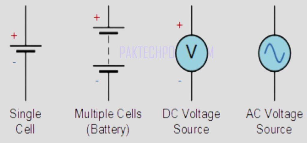
Batteries, power supplies, or solar cells are examples of DC (direct current) voltage source which produce fixed value and polarity, for example, 3V, 5V, 10V, etc. While AC voltages are used in home, industries and factories. The voltage and frequency of mains AC electricity used in homes is typically 230 volts AC (230V) in the United Kingdom and 110 volts AC (110V) in the USA.
Electronic circuit range is between 1.5V and 24V DC. The circuit symbol for a constant voltage source is usually depicted as a battery symbol with a positive (+) and negative (-) sign indicating the direction of the polarity. Sine wave is symbol of alternating voltage source.
Voltage Symbols.

Example of Potential Difference:
Water Tank Analogy:
Imagine two water tanks at different heights connected by a pipe. The height difference between the two water tanks represents the potential difference (voltage) in an electrical circuit. Water will flow from the higher tank to the lower tank due to the difference in gravitational potential energy, similar to how electrical current flows from a point of higher voltage to a point of lower voltage in a circuit. The greater the height difference (potential difference), the greater the pressure (voltage) that drives the water (current) flow.
What is Electrical Current?
Electrical current is the flow of electric charge through a conductor or circuit. This flow is driven by a potential difference (voltage) and is typically carried by electrons moving through a wire or other conductive material. The unit of measurement for electrical current is the ampere (A), which represents the flow of one coulomb of charge per second. Electrical current can be either direct current (DC), where the flow of electrons is in a single direction, or alternating current (AC), where the flow of electrons periodically reverses direction.
In practical terms, electrical current is what powers our electronic devices and appliances. For instance, when you plug in a lamp and switch it on, the current flows from the power source through the lamp’s circuit, causing the bulb to light up. Similarly, in a car, the battery provides current to start the engine and power the electrical systems. Understanding electrical current is crucial for designing and troubleshooting circuits, as it helps in determining how much charge is moving through the system and ensuring that components are properly powered without being overloaded.
What is Conventional Current Flow?
Conventional current flow is the hypothetical flow of positive charges from the positive terminal to the negative terminal of a power source in a circuit. This concept was established before the discovery of the electron and is based on the assumption that electric current flows from the positive side to the negative side. In reality, electrons, which carry a negative charge, move from the negative terminal to the positive terminal. However, conventional current flow is still widely used in circuit diagrams and analysis for consistency and historical reasons.

Despite the fact that the actual movement of charge carriers in most conductors (like metals) is due to electrons moving in the opposite direction, conventional current flow remains a useful and standard way of describing the direction of current in electrical engineering and physics. It simplifies the understanding and communication of circuit behavior, as most circuit components and mathematical models are designed using this convention. For example, when analyzing circuit diagrams, engineers use conventional current flow to determine the direction of current through various components, even though the electrons are moving in the opposite direction.
What is Electron Flow?
Electron flow refers to the movement of electrons from the negative terminal to the positive terminal of a power source in a circuit. This flow occurs because electrons, which are negatively charged, are repelled by the negative terminal and attracted to the positive terminal. Electron flow is the actual physical movement of charge carriers in conductive materials, such as metals, where free electrons move through the atomic lattice of the conductor.

Understanding electron flow is crucial for explaining the underlying mechanisms of electrical phenomena. For instance, when a battery is connected to a circuit, the chemical reactions within the battery create a surplus of electrons at the negative terminal. These electrons then flow through the circuit towards the positive terminal, powering any connected devices along the way. While conventional current flow is often used for simplicity and standardization in diagrams and calculations, electron flow provides a more accurate representation of what is happening at the microscopic level within the conductors of an electrical circuit.
Resistance Theory of DC Circuit.
Resistance is a measure of how much a material or component opposes the flow of electric current through it. It determines how easily or difficultly current can pass through a conductor. The higher the resistance, the more it resists the flow of current. Resistance is dependent on factors such as the material’s properties, temperature, length, and cross-sectional area of the conductor.
The unit of resistance is the ohm (Ω). It can also represent kΩ (103 Ω), MΩ (106 Ω). One ohm is defined as the resistance that allows a current of one ampere to flow when a voltage of one volt is applied across it.
In most practical situations, resistance is a positive value. A negative resistance is a theoretical concept rather than a real physical property of materials. In certain active components like tunnel diodes or in specific circuits, a negative differential resistance can occur, where an increase in voltage across the component results in a decrease in current. However, this is a special case and not the typical behavior of resistance in standard materials and components.
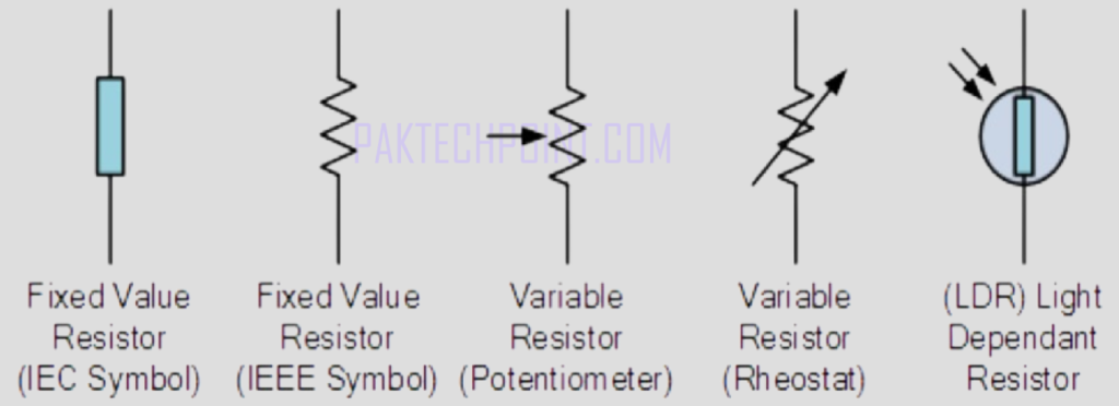
Resistor Symbols.

Materials that allow electric current to flow through them easily are called good conductors. Good conductors are typically metals, and they have a high density of free electrons that can move through the material when a voltage is applied.
Materials that do not allow electric current to flow through them easily are called bad conductors or insulators. Insulators have very few free electrons available to move through the material.
Standard Resistance Values of Materials:
Copper is one of the best conductors of electricity. For a standard copper wire of 1 meter length and 1 mm² cross-sectional area, the resistance is about 0.017 ohms.
Aluminum is also a good conductor, though not as good as copper. For a standard aluminum wire of 1 meter length and 1 mm² cross-sectional area, the resistance is about 0.028 ohms.
Carbon is a poor conductor compared to metals, but it is better than many non-metals. For a standard graphite rod of 1 meter length and 1 mm² cross-sectional area, the resistance is about 35 ohms.
Is resistor is active or passive element?
A resistor is considered a passive element in electrical and electronic circuits.
A passive element is a component that does not generate energy but can store, dissipate, or release it. Passive elements do not require an external power source to operate and cannot amplify a signal. Examples of passive elements include resistors, capacitors, and inductors.
What is Conductance?
Conductance is a measure of how easily electric current can flow through a material. It is the reciprocal of electrical resistance, indicating how well a material can conduct electric current.
The unit of conductance is the siemens (S), named after the German scientist Werner von Siemens. Another older unit is the mho (℧), which is simply “ohm” spelled backward.
Relationship with Resistance:
- Conductance (G) and resistance (R) are inversely related. This means that if a material has high resistance, it has low conductance, and vice versa.
The mathematical relationship between conductance and resistance is given by:
G = 1/R
Where: ( G ) is the conductance in siemens (S) and ( R ) is the resistance in ohms (Ω).
Practical Example:
If a resistor has a resistance of 10 ohms (Ω), its conductance can be calculated as:
G=1/R=1/10 Ω=0.1 S
Formulas for Conductance.
i = 1/R * v = Gv. OR p = i2/G = v2G.
The relationship between voltage (V) and current (I) in a circuit with constant resistance (R) produces a straight-line I-V graph, where the slope of the line equals the value of the resistance. This indicates that current is directly proportional to voltage when resistance remains constant, as demonstrated by Ohm’s Law.
