EXPLAIN THERMOCOUPLE CONSTRUCTION AND TYPES OF THERMOCOUPLE
This article is about CONSTRUCTION AND TYPES OF THERMOCOUPLE and focusing to the engineers, technicians and supervisors. You will find lot of documents related to this article. Just navigate our website www.paktechpoint.com and find more articles. Please! Do not forget to subscribe our You tube channel also. Thanks in Advance. PLEASE SUBSCRIBE OUR PAKTECHPOINT YOUTUBE CHANNEL
EXPLAIN THERMOCOUPLE CONSTRUCTION AND TYPES OF THERMOCOUPLE
A thermocouple made up with two dissimilar metal wires like constantan and iron and make sensing element by joining at one end which is called hot junction. we have two ends of thermocouple, one end is attached with transmitter or voltmeter which cold junction and 2nd end is connected within process which is hot junction. Please following figure
Figure Thermocouple
Principle of Thermocouple
Applying heat to the measuring junction causes a small emf to be generated at the reference junction. When a readout device is employed, it converts the emf produced by the temperature difference between the measuring and the reference junctions to record or otherwise display the temperature of the measuring junction. When the reference temperature is known (usually 0°C) and the measuring junction is exposed to an unknown temperature, the emf developed will vary directly with changes in the unknown temperature.
Types of Thermocouple
Several types of T/Cs are available, each different type by the meterials which is used to construct the element. The T/C categories are:
Type (E) —Chromel and constantan
Type (J) —Iron and constantan
Type (K) —Chromel and alumel
Types (R and S) —Platinum (Pt) and rhodium (Rh) (differing in the % of platinum)
Figure shows the comparison of 5 types of thermocouples.
Figure Thermocouple types
Figure Thermocouple color codes
TYPE E
Type E thermocouples (chromel-constantan) are gaining popularity because they have the highest output (most sensitive) and can be used over a wide range of temperatures.
Type J
Type J thermocouples (iron-constantan) are among the first thermocouples to be widely used. The materials are rugged, but iron wire is susceptible to oxidation, especially at high temperatures. The corrosive effects of oxidation (poisoning) reduce the accuracy of the T/C. Type J T/Cs remain one of the most common T/C types in use today.
Type K
Type K thermocouples (chromel-alumel) are commonly used for high-temperature applications. Because they are relatively inexpensive and offer a wide measurement range. Type K T/Cs are the most popular T/C type in industrial environments.
Types R and S
Types R (Pt/13%Rh, Rh) and S (Pt/10%Rh, Rh) thermocouples are useful for extremely high temperature measurements. Because they are constructed from a platinum alloy, types R and S T/Cs are expensive and are used only when the process temperatures are too high for other T/Cs to function properly.
Type T
Type T thermocouples (copper-constanan) are generally used in very low temperature (cryogenic) applications. Type T T/C elements are good when moisture may be present.
Hot Junction Configurations
Thermocouple have four types of Junctions. Grounded, ungrounded, Isolated and unisolated. Each junction cnfiguration has its own limitation and benefits. T/C Junctions are grounded and ungrounded with sensor sheath.
we may have two thermcouples in one sheath and it can be isolated or connected/unisolated.●Grounded T/C
Grounded T/C has faster and quick response and more susceptible to electrical noise. Note: This noise can corrupt the voltage signal. It creates improved thermal conductivity.
●Ungrounded T/C
As compare to grounded, ungrounded has slower response time. And this type of junctions are not susceptible to electrical noise.
●Isolated
If junctions are Isolated , of course reliability of each junction will be increased, but one junction fails it does not cause to disturb to other junction.
●Unisolated
Unisolated junctions are at the same temperature, but both junctions will typically fail at the same time.
Figure T/C Junction Configurations
VOLTAGE MEASUREMENT AND THE SEEBECK Effect
T/Cs use a term which is called as the Seebeck effect to describe the process temperature. Seebeck Effect – When two wires consisting of dissimilar metals are bonded at both ends and one of the ends is heated, a continuous current will flow in a circuit, called a “thermoelectric circuit.” The current flows whenever there is a temperature difference between the two junctions. This phenomena is called the Seebeck Effect, named after Thomas Seebeck who discovered the existence of thermoelectric circuits.
If you were to break open the thermoelectric circuit and measure the voltage at one end, the voltage would be a function of the temperature difference between the junctions and composition of the metal wires. This voltage is called the Seebeck voltage (Figure 24), the thermoelectric voltage, or the thermoelectric EMF. All dissimilar metals exhibit this effect.
Figure Seeback Voltage
If the hot junction temperature is held constant, an increasing cold junction temperature will produce a decreasing voltage, because the temperature difference between the hot and cold junction is decreasing. When the cold and hot junctions reach the same temperature, the observed voltage will be 0 V. The magnitude of the voltage signal produced at the cold junction also depends on the type of metals used to form the T/C. Different metals, or different type of T/Cs, have different thermoelectric voltages at the same temperatures.
Cold Junction Compensation
As we already mention about cold junction in this article, the junction where T/C lead wires are attched to transmitter. So we must know the cold junction voltage because to determine the voltage and temperature we always measured at cold junction point, and voltage which is measured in cold junction proportional to difference of temperature in cold and hot junction.
The process of factoring the cold junction temperature rather than considering it is 0c, it is called cold junction compensation. RTD or T/C has curve which is standard curve at temperature of 0c. which describes the voltage versus temperature relationship.
The general steps for performing CJC are as follows:
Determine the temperature of the cold junction (room temperature) and find the corresponding voltage (CJV) in the thermocouple table
With the hot junction exposed to the process temperature, read the voltage output.
Add the measured process temperature voltage to the cold junction voltage (CJV) and look up the result in the thermocouple table to find the true process temperature.
Thermocouple Extension Wire
In practice, it is not always practical to connect the thermocouple directly to an instrument.T/C extension wires are often used to wire the T/C back to a control system or to a remote transmitter, which may be anywhere from 2–2,000 ft away.
T/C extension wire, with a few rare exceptions, must be of the same type of metal with similar thermal characteristics as the thermocouple.
Extension wires theoretically extend the thermocouple to the reference junction in the instrument with similar thermal characteristics as the thermocouple. This wire is generally furnished in the form of a matched pair of conductors. The simplest procedure is to use the same types of wire that the T/C itself is made of; however, in installations with noble-metal T/C where several hundred feet of extension wire must be used, or where numerous T/C are employed, such a procedure may become too expensive. In such cases alternative, lower-cost materials with similar characteristics at lower temperatures are available
Figure Extension wire type with polarity
The thermocouple’s signal is often sent to a remotely located instrument. The connection is made through the use of thermocouple extension wire. Extension wire is often made from the same type of material as the thermocouple. For example, Type J extension wire is used with a Type J thermocouple only, and likewise for other types of extension wire and thermocouples. At one time, it was a common industrial practice to install the extension wire from the thermocouple to the measuring instrument, ideally in one continuous wiring length.
A standard practice in industry is to use extension wire from the thermocouple to a local junction box dedicated to thermocouple signals. The use of a 16 gauge extension wire is a standard industry practice. A multipaired cable is used from the local junction box to the the indicating instrument. Each cable pair is twisted and individually shielded. Multipaired cables are available with up to 50 pairs of wires manufactured to the same calibration as the thermocouple. Cables are made for only one type of extension wire in a cable.
It is important to select the correct extension wire, because the use of an incorrect extension wire will cause errors in temperature readings. The errors are caused by the creation of extra thermocouple junctions at the terminal blocks or in the measuring instrument.
Some of the causes of incorrect thermocouple measurements are the following:
• Noise rejection – Proper shielding, filtering, and grounding corrects this problem.
• Poor junction connections – Vendors weld measuring junctions on sophisticated machinery to ensure proper welds and uniform products. When personnel make their own T/Cs, the improper welding of a junction can actually degrade and change the junction’s characteristics.
• Decalibration – Decalibration represents a process of unintentionally altering the characteristics of the T/C through rough handling, vibration, aging, or exposure to temperature extremes.
Electrical noise pickup by instrument circuits will cause errors. The following types of noise can be distinguished:
• Static noise may be introduced into T/C circuits by adjacent wires carrying AC power or rapidly varying (pulsating) DC. (Remedy: Minimize the resultant noise by shielding each pair of extension wires and grounding the wire shields. Never run T/C wires in the same conduit with electric power wires.)
• Magnetic noise may be induced into a T/C circuit any time the extension wires are subjected to a magnetic field and a current is produced to oppose the magnetic field. (Remedy: Minimize the noise by twisting each pair of T/C extension wires.)
Crosstalk noise between adjacent wire pairs in the same conduit may occur.
( Remedy: Shield each pair of extension wires. )
• Common-mode noise in the circuit between measuring junction and transducer may occur when the circuit is grounded in more than one place, or when different
grounding potentials exist along the wire path.(Remedy: Minimize by proper grounding. T/C circuits usually are grounded at the measuring junction. Shield each pair of extension wires and ground the shields at the T/C only.)
Diagnosing thermocouple errors is accomplished through several techniques. The following checks can be performed on a suspect thermocouple:
• Resistance checks can identify problems. Low resistance usually means the T/C is OK, high resistance could mean the T/C is open or has a loose connection.
• Polarity of connections is very important. An extension wire’s positive connection must be made to the positive connection of the sensor. A large temperature error, up to 100°C on a Type K thermocouple, can occur if polarity is reversed. Because the Type K’s positive connection is magnetic, and the negative connection is nonmagnetic, polarity can be checked with a small magnet.
• Visually examining the hot junction, the extension wires, and connectors can reveal trouble spots.
• Portable calibrators can verify signal integrity.
3 thoughts on “EXPLAIN THERMOCOUPLE CONSTRUCTION AND TYPES OF THERMOCOUPLE”
Hello. I have checked your paktechpoint.com and i see you’ve got some duplicate
content so probably it is the reason that you don’t rank high in google.
But you can fix this issue fast. There is a tool that rewrites content like human, just search in google: miftolo’s tools
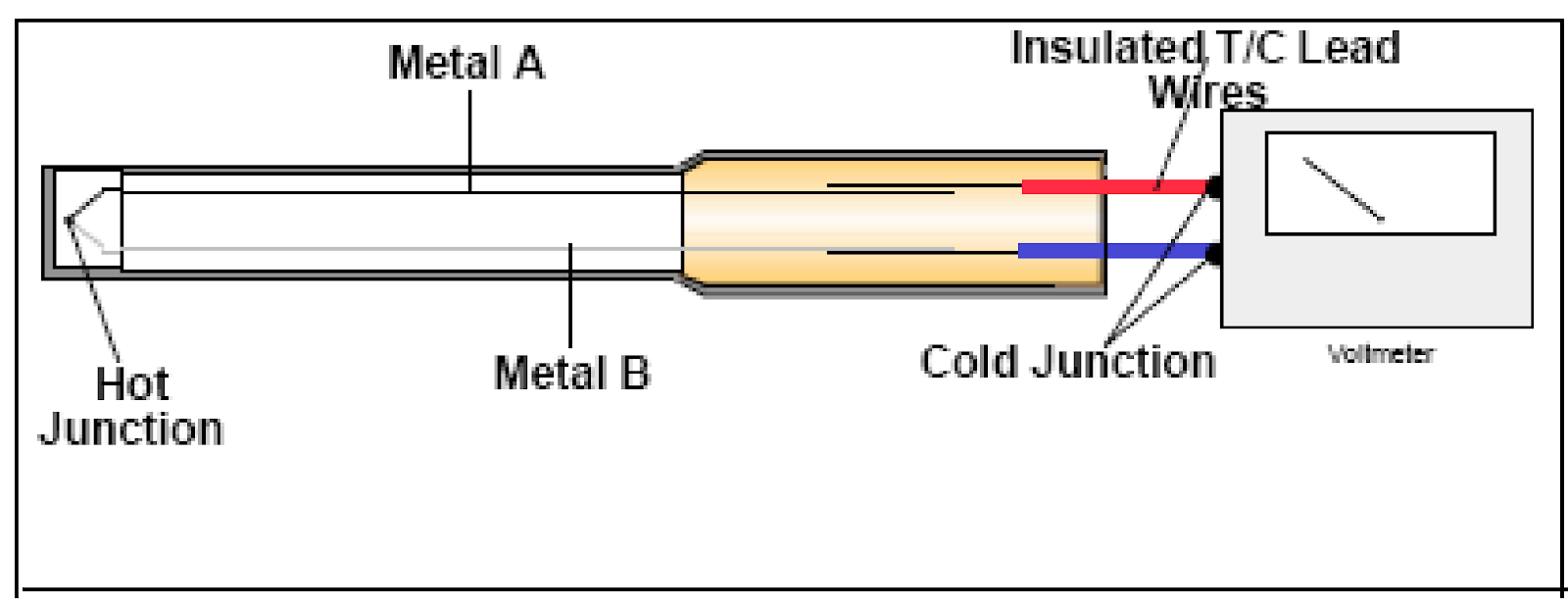
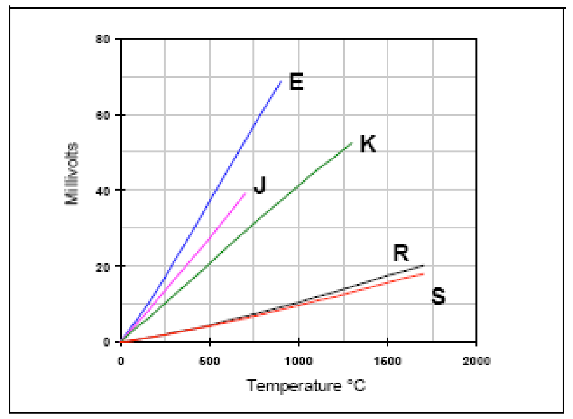


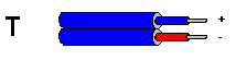


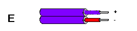
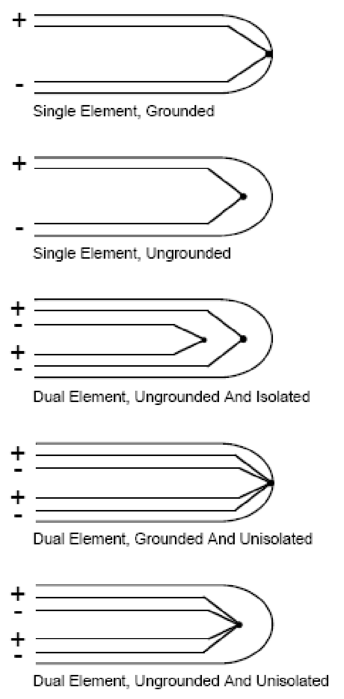
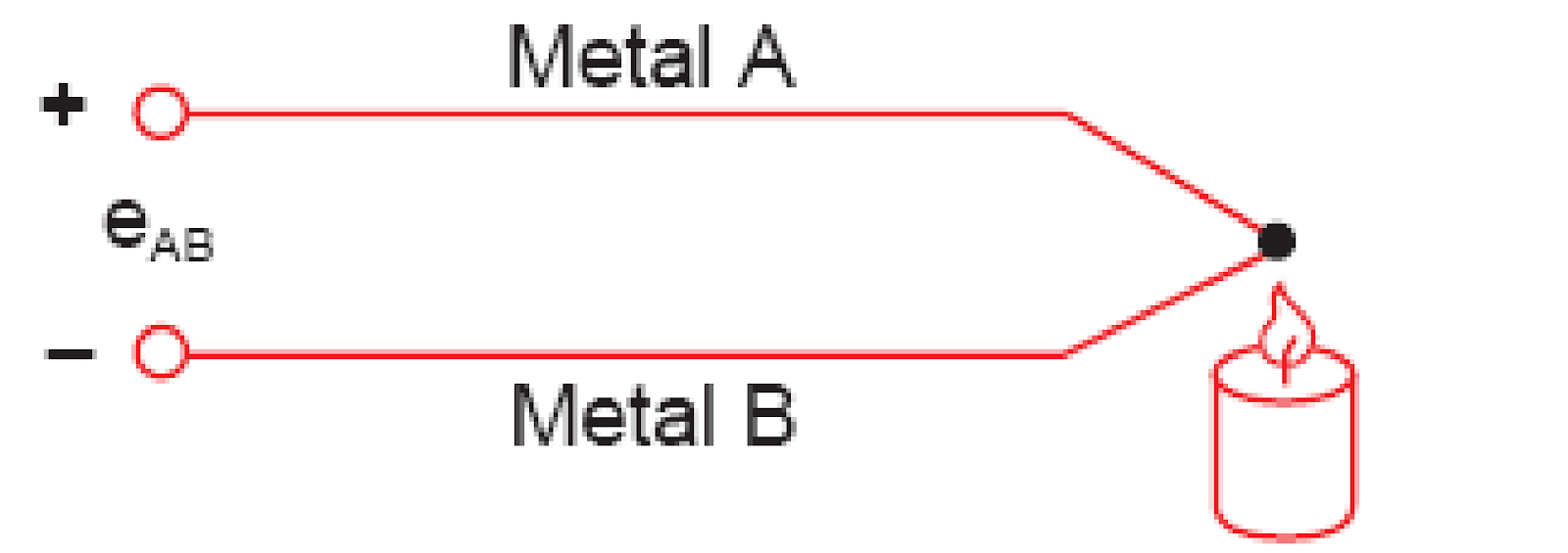 Figure Seeback Voltage
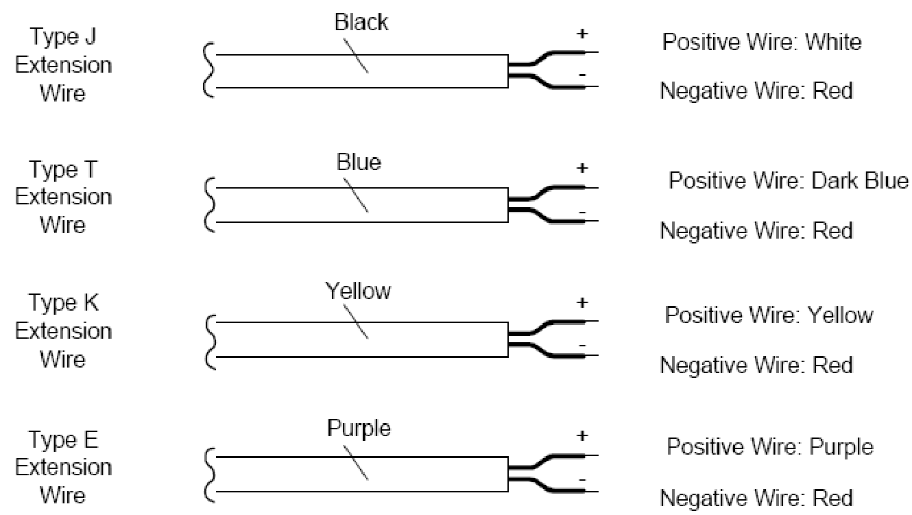
Knowledge able information
Hello. I have checked your paktechpoint.com and i see you’ve got some duplicate
content so probably it is the reason that you don’t rank high in google.
But you can fix this issue fast. There is a tool that rewrites content like human, just search in google: miftolo’s tools