In industrial environments, high process temperatures, pressures, and vibration make it necessary to have a robust temperature sensor. Fast response time, accuracy, and stability are also needed. While several types of temperature sensors are available, the two most commonly used in the process measurement industry are resistance temperature detectors (RTDs) and thermocouples (T/Cs). Here we will discuss RTD CONSTRUCTION AND TYPES OF RTD briefly.
RTD CONSTRUCTION AND TYPES OF RTD
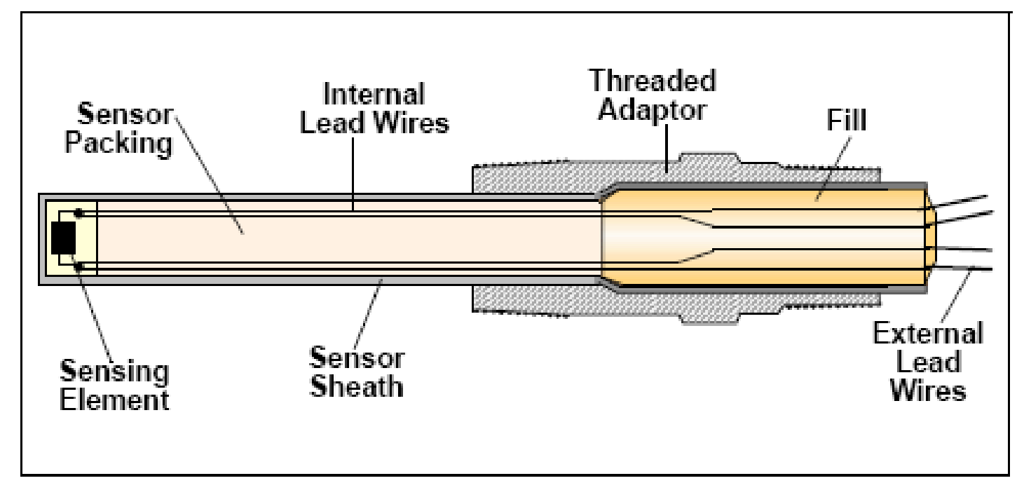
RTDs and T/Cs have several construction characteristics in common.
They are :
*Sensing element
*Lead wires
*Sensor sheath
* Threaded adaptor (optional)
Figure Common Temperature Sensor Characteristics
SENSING ELEMENT
The sensing element (RTD element or T/C hot junction) is the actual temperature sensing unit which is located at the tip of the temperature sensor, on the end that is exposed to the process temperature. The sensing element, which is constructed of metal, responds to the process temperature by generating a measurable resistance (in RTDs) or voltage (in T/Cs) signal.
LEAD WIRES
Lead wires are attached to the sensing element and then passed through the sensor sheath. The lead wires are insulated before exiting the sensor sheath. Lead wires connect the sensing element either directly to the DCS or to a temperature transmitter connected to a DCS.
SENSOR SHEATH
The sensor sheath is constructed of metal and holds most of the component parts of the temperature sensor. The sensor packing, typically magnesium oxide (MgO), surrounds the sensing element and is contained within the sensor sheath. The sensor packing decreases the impact of process vibration on the sensing element and thus ensures a more accurate measurement. The end of the sensor sheath is sealed with a fill (e.g., epoxy) that keeps moisture out of the sheath and away from the sensing element.
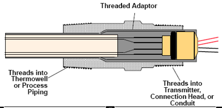
The threaded adaptor is welded over the rear housing of the sensor sheath. One end of the threaded adaptor threads into a thermowell or directly into the process piping. The other end is
typically threaded into a temperature transmitter, connection head, or conduit connection.
Figure Threaded Adaptor
RESISTANCE TEMPERATURE DETECTOR (RTD)
How RTD works? It works on principle of electrical resistance with directly proportional to temperature, this is called thermoresistivity. So We can predict for temperature by measuring the resistance of RTD.
Principle of Operation
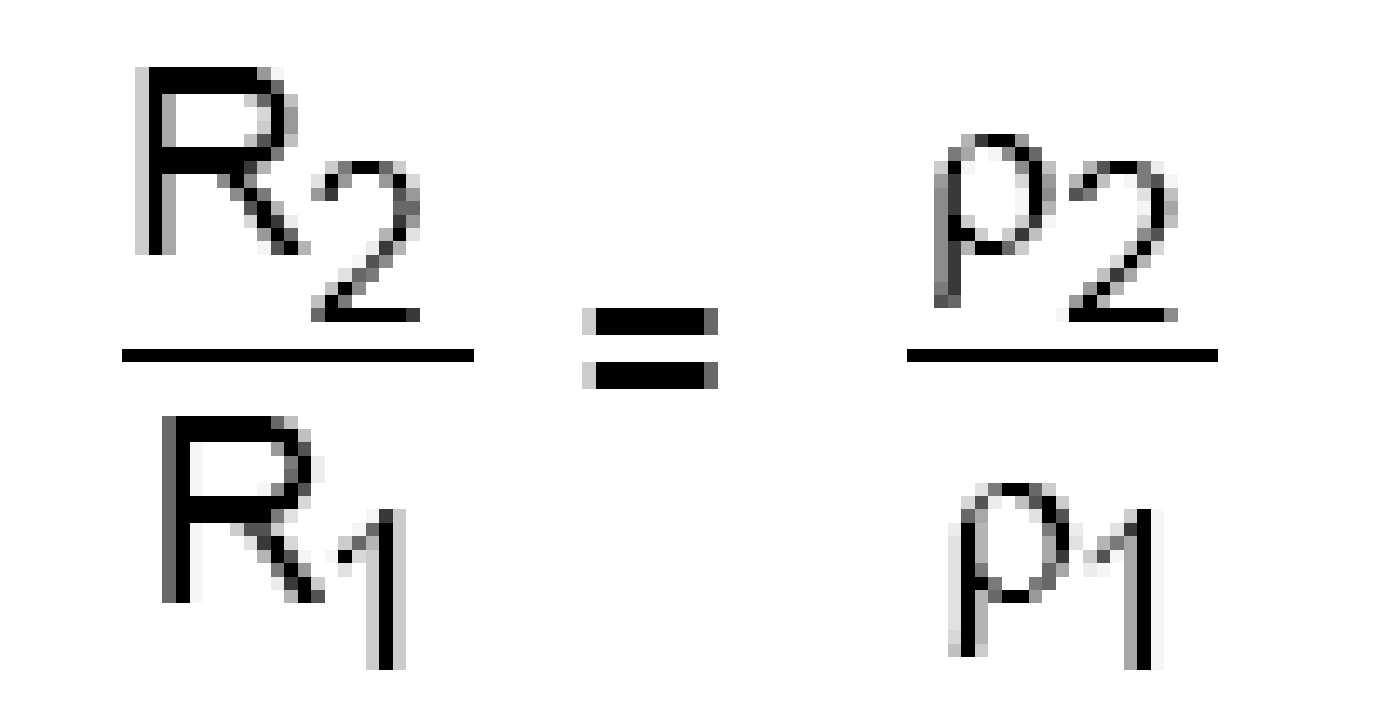
Given a piece of wire of length “l,” area “a,” and resistivity “ρ,” the resistance of
This piece of wire is given as
where:
ρ = Resistivity in Ω – cm
R = Resistance in ohms (Ω)
l = Length in cm
a = Cross-sectional area in cm2
ρ is a function of the material of the wire and temperature of the wire; e.g., given a piece of copper wire, l cm long and having an area = a in cm2, the resistance of this wire is now a function of the temperature.
where T1 > T0
Hence
And for most conductors (except carbon), ρ changes depend on α, the temperature coefficient of resistance. α is different for different materials and
Rt ≅ Ro (1 + αt)
Ro = resistance at a reference temperature, 0°C
Rt = resistance at temperature, t
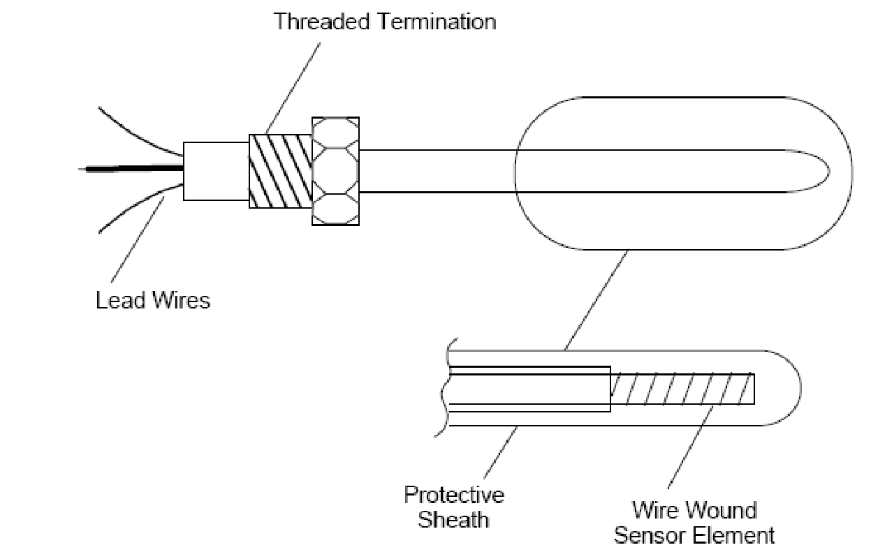
This change in ρ is completely predicable and reproducible for many materials. The material chosen for an RTD is chosen for its large α, linearity, and temperature range. The conductive material is most often platinum. The most common configuration of an RTD is a probe form.
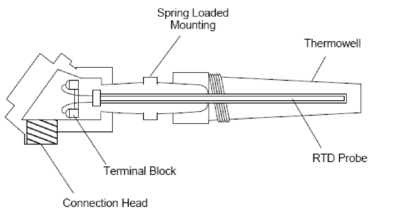
An RTD probe consists of a protective sheath, which is often a closed-end stainless steel tube, a sensor element, lead wires, and a threaded termination.
Figure RTD Probe Construction
Although an RTD probe has a protective sheath, it can be inserted into a thermowell for added protection from process contaminants.
Figure RTD inserted in a Thermowell
RTD SENSING ELEMENT MATERIALS
Mostly characteristics of RTD can be expressed based on matrial used for RTD like metal or alloy. To be useful in an RTD element, the metal or alloy must have the following characteristics:
A predictable relationship between temperature and resistance
Relatively high resistance that can be measured easily
Physical strength
Stability (will not melt or freeze) over the measured temperature range
A large, easily measurable change in resistance for a given change in temperature.
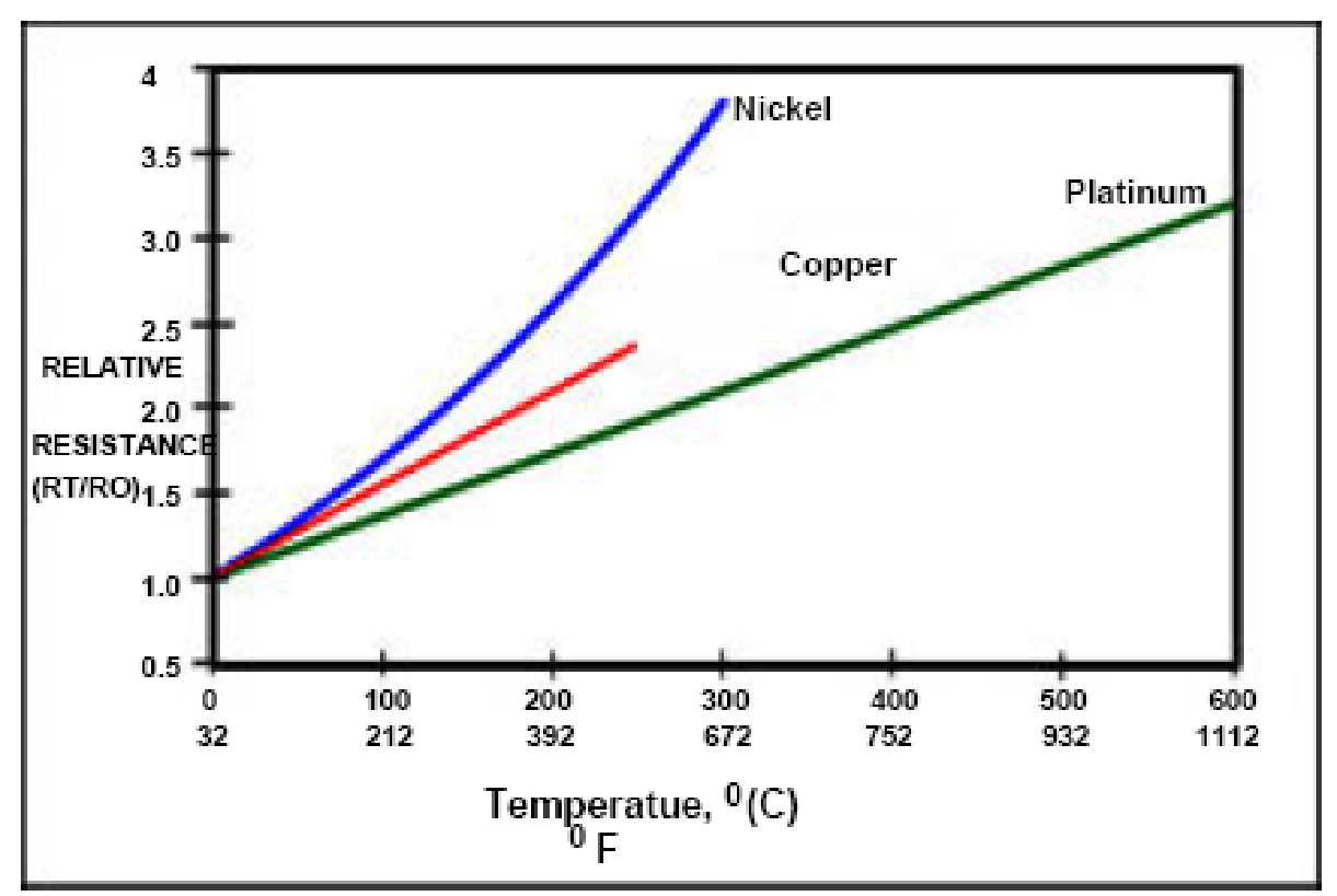
The three types of resistance metals most commonly used to construct RTDs are platinum, copper, and nickel.
Platinum
Platinum RTD elements are the most common type of RTD element used in process industries. Platinum elements have high accuracy, high repeatability, and a high resistance change per degree of temperature change. In addition, platinum RTD elements are highly linear throughout their temperature range.
Copper
Copper RTD elements are highly linear throughout their temperature range, but have limited accuracy and a narrower temperature range than platinum elements. Copper elements are most often used for measuring temperature in bearings and motor windings—applications in which accuracy is not critical.
Nickel
Nickel RTD elements have a high resistance change per degree of temperature change, but have poor linearity, limited accuracy, and a relatively narrow temperature range. Nickel elements are most commonly used in applications in which accuracy is not critical. Figure18 compares thermoresistive characteristics for platinum, nickel, and copper RTD elements. (Note the platinum element’s wider temperature range and more linear.
Figure RTD Elements Thermoresistive Comparison
RTD SENSING ELEMEMENT RESISTANCE MEASUREMENT
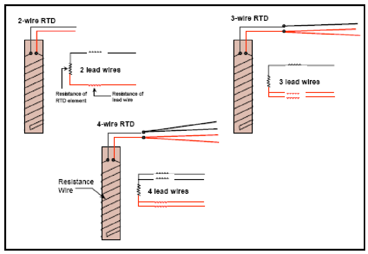
When you want to get exact measurement of temperature , you should measure the resistance of RTD. How much is error can be expected for RTD, for copper wire which is connected to sensing element of RTD adds some amount of resistance in temperature measrement. this additional resistance must be observed, if you ignore this resistance, you will face some error in temperature reading. This phenomenon is called lead wire effect of RTD. Now it depends upon the length of wire running, greater the length greater will be error or lead wire effect in temperature measurement. Now you will get answer of why we use three wire or four-wire RTDs instead of two-wire RTDS. Thats why! Happy! For compensation of these lead wire resistance.
In three wire RTD, we add only one additional copper wire to the lead wires and in four wire RTD, we add one additional copper lead wire with each existing lead wires.
Figure Two wire, Three wire and 4 wire RTDs.
Two-Wire RTDs
Two-wire RTDs cannot compensate for lead wire effects. Resistance of the two lead wires is added into the resistance of the RTD element, which results in an inaccurate temperature reading. A small lead resistance can introduce significant error into the measurement of output temperature.
For example, a 10 Ωlead wire on a field-mounted RTD implies a 10 Ω/0.385Ω/°C = 26°C error in a measurement.
Three-Wire RTDs
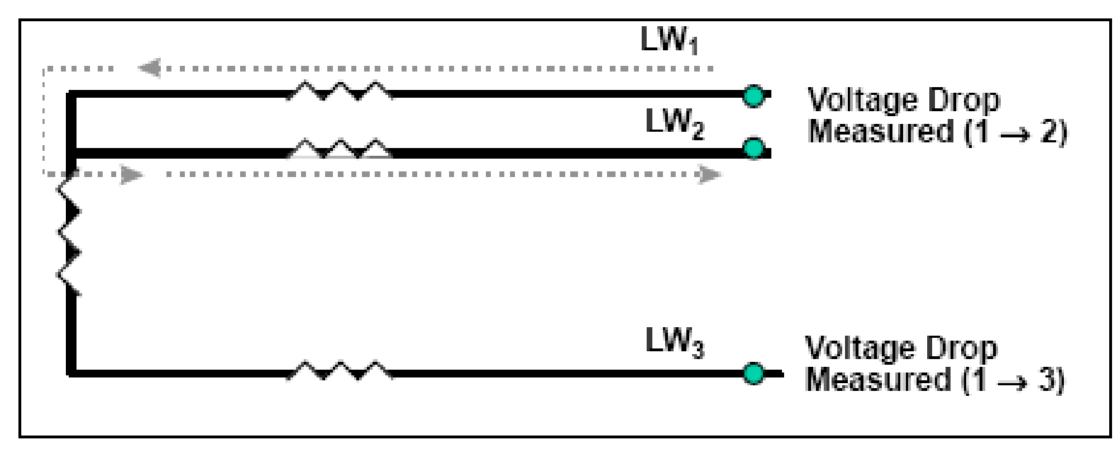
Three-wire RTDs allow for compensation of lead wire effects. There are several methods for performing lead wire compensation and finding the resistance of the RTD element. One common method uses Ohm’s law (Voltage [V] = Current [I] × Resistance [R])
A small, known current is sent through LW1 and LW2 (Figure 20), and the voltage drop across LW1 and LW2 is easured.
The resulting value is used later in the calculation.
Figure Lead wire compensation for 3 wire RTD
Next, the voltage drop across LW1 and LW3 is measured. The resulting value includes the effects of the lead wires.
From Ohm’s law, the resistance of the RTD element plus the lead wires is equal to the measured voltage drop divided by the known current (R = V/I).
To find the voltage of the RTD element alone, the lead wire voltage of LW1 and LW3 must be subtracted from the measured voltage across LW1 and LW3. The voltage of LW1 and LW2 found in Step 1 can be used as a close approximation to the voltage of LW1 and LW3.
Calculate the resistance of the RTD element using Ohm’s law. (Some error may still be present since Vlead wires 1&3 will never exactly equal Vlead wires 1&2).
Three-wire RTD lead wire compensation is less accurate than four-wire RTD because of the assumption that the resistance of LW2 and LW3 is equal.
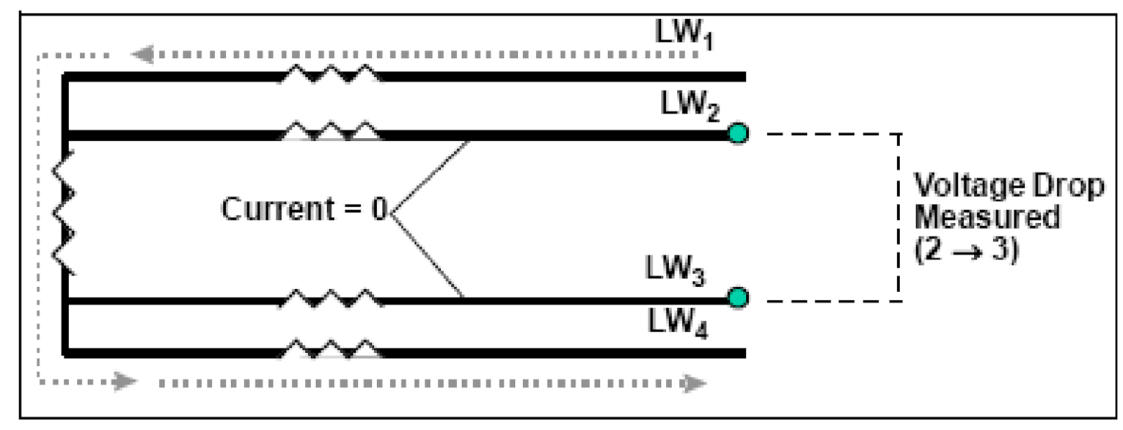
Four-Wire RTDs
Four-wire RTDs provide the best lead wire compensation. A constant current is passed through the outer lead wires LW1 and LW4 ( see fig 21 ). Because the voltage drop is measured across lead wires LW2 and LW3 (i.e., no current flows through lead wires 2 and 3), all that is measured is the resistance of the RTD.
Figure Lead wire compensation for 4 wire RTD
Therefore,
Installation precautions:
Slow Dynamic response: The RTD sensing element consists of an encapsulated wire cut to a length that gives a predetermined resistance at 0°C. The temperature sensitive portion of the probe, which depends on the length of the sensing element, is from 0.5 to 2.5 in. The RTD is
thus considered to be an area-sensitive device, and has a significantly slower dynamic response than point-sensitive devices (like T/C).
Remedy: This problem is of little importance. RTDs are invariably installed in thermowells. Because these thermowells represent a major contribution to the slowing of the dynamic response, the minor differences between RTD and other sensors are insignificant.
Self-heating Effect
The RTD is a passive resistance element, and a current must be applied to it to develop an output signal. This current generates heat, which becomes objectionable when it is sufficient to significantly change the temperature to be measured.
Remedy:
Use only a limited amount of power to produce the output signal; however, the self-heating effect is difficult to specify quantitatively, because the heating depends on the configuration of the RTD element, and its environment (e.g., fluid velocity past the element).
Standardization-
Lack of standardization among manufacturers concerning the relationships between resistance and temperature may cause an accuracy problem when RTDs of several manufacturers are used in a single system, or when the element of one manufacturer is replaced with the element of another manufacturer.
Remedy:
Do not mix RTDs with different temperature vs. resistance curves.
Lead Wire Configuration –
Copper Lead Wire for connection of an RTD to the transducer, although a satisfactory trade-off between cost and resistance, represents a resistance in series with the RTD and thus is a source of inaccuracy. For long transmission distances, ambient temperature effects can cause appreciable errors.
Remedy: Compensate for lead wires and connection effects by designing the RTD as a 3- or 4-terminal device.
5 thoughts on “EXPLAIN RTD CONSTRUCTION AND TYPES OF RTD”
rtd construction types good article
rtd explanation