This article is about TEMPERATURE TRANSMITTER CALIBRATION & CHECKING OF TEMPERATURE SENSORS and focusing to the engineers, technicians and supervisors. You will find lot of documents related to this article. Just navigate our website www.paktechpoint.com and find more articles. Please! Do not forget to subscribe our You tube channel also. Thanks in Advance.
PLEASE SUBSCRIBE OUR PAKTECHPOINT YOUTUBE CHANNEL
TEMPERATURE TRANSMITTER CALIBRATION & CHECKING OF TEMPERATURE SENSORS
Calibration of Resistance Temperature Device (RTD) Temperature Transmitter
- Check temperature transmitter against data sheet.
- Connect as per attached hook-up drawing.
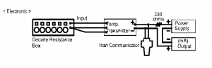
RTD Type Temperature Transmitter
- Ensure that all polarities are correct and all connections are tight. Connect HART Communicator red wire to positive, black to negative.
- Switch on power supply and HART Communicator unit.
- Check that the ID of thetransmitter is correct.
- Using RTD tables, inject 0% input with the Decade Box and note that the output should be 4mA on the multi meter.
- Inject 25%, 50%, 75%, & 100% of the range to the transmitter and note that the output shall be 8mA, 12mA, 16mA and 20mA respectively.
- Then proceed in the reverse direction from 100% to 0%.
- If the error is greater than the allowed tolerance, inject 0% to the input of the transmitter and using the HART Communicator, adjust transmitter until output reads 4mA.
- Inject 100% input and adjust accordingly. The output should be 20mA or 100%.Repeat steps above until accuracy is within required tolerances.
- If accuracy is within required tolerances, repeat steps above and record the reading.
- Apply 110% signal as check for hysteresis.
- Turn off power supply. Disconnect all wiring and replace cover tightly. After the test has been completed, the instrument shall be identified with a color code sticker.
Results shall be filed and recorded on applicable forms.
Please read also: EXPLAIN RTD CONSTRUCTION AND TYPES OF RTD
Resistance Temperature Device (RTD) Chekcing
- Manufacturer’s test routines shall be followed and calibrations to be confirmed within tolerance limits. Manufacture’s test procedures shall be confirmed and verified. (MC5 Multifunction Calibrator) Sheath shall be removed from the thermo well and checked for damage.
- Resistance between terminals shall be measured and recorded. Measured resistance value shall be compared with the value obtained from the conversion chart corresponding to ambient temperature. If accuracy is within required, then it is acceptable.
- Resistance between terminals and sheath shall be checked. Terminals and sheath shall be isolated from each other. Refer to instrument data sheet as specific reference. Verification by Temperature controlled Bath Response of the RTD’s O/P (ohms), shall be verified using a Temperature controlled bath for higher temperature, not only ambient temperature measurement.
- After testing, sheath shall be replaced in their thermo well. It is important that the sheath be “bottomed” in the thermo well.
- After the test has been completed, the instrument shall be identified with a color code sticker.
- Results shall be filed and recorded on applicable forms.
Thermo well checking
- Manufacture’s special test procedures if any, shall be confirmed including the following statements below.
- Thermo well shall be identified by their tag numbers and checked against their respective data sheets.
- Thermo well shall be checked for their correct stamp and tag.
- All dimensions shall be checked against their data sheets as well as for their service, line numbers, line size and material.
- Results shall be filed and recorded on applicable forms.
Temperature Gauges checking
- The temperature Gauges shall be checked in accordance with the specification.
- The instrument shall be checked at five (5) points low, mid and high using a temperature controlled bath.
- The readings shall then be noted in the calibration certificate.
- After the test has been completed, the instrument shall be identified with a color code sticker.
- Results shall be filed and recorded on applicable form.