There are two main forms of fatigue on the metals, the mechanical fatigue and the thermal fatigues. Both of these fatigues result in weakening and failure of the metals at the localized areas which undergo the metallurgical changes due to applied cyclical stresses well below the plastic deformation stress values, for specified period of time.

Most vulnerable are the unsupported small bore piping attached to the system containing pumps and compressors which induce the cyclic stress on the adjacent structures. The anchoring points of the lines which shake due to liquid hammering and frequent rapid flow like relief piping are also affected by fatigue.
Fatigue in Mechanical Engineering.
Since all forms of fatigues are the metallurgical changes, the earlier detection of the fatigue is possible by the Eddy Current and electrical resistance measurement methods.
1. Mechanical Fatigue.
Metals subjected to a repetitive dynamic loading for a certain period of time fail at a stress level much lower than that required to cause fracture on a single application of load.
Such failures occurring under conditions of dynamic loading are called fatigue failures.
The period after which the failure occurs varies and depends of the alloy composition. Theductile metals usually require higher number of loading before failure called as higher endurance. A fatigue failure is particularly dangerous because it occurs without any obvious warning. Fatigue results in a brittle‐appearing fracture, with no gross deformation at the fracture.
A fatigue failure can usually be recognized from the appearance of the fracture surface, which shows
- A smooth region, due to the rubbing action as the crack propagated through the section, and
- A rough region, where the metal has failed in a ductile manner when the cross section was no longer able to carry the load.
- Mostly the progress of the fracture is indicated by a series of rings, or “beach marks”, progressing inward from the point of initiation of the failure.
Because of widely varying response of different metals towards fatigue the exact prediction of the fatigue failure is not possible, however the empirical models can be developed to assess amplitude and safe number of cycle that can be applied on the metal to avoid failure. The main factors contributing to the fatigue of the metal are following.
- Number and amplitude of cyclic loadings.
- Maximum tensile stress on the metal.
- Orientation of cyclic stress as compared to the direction of rolling (or formation) on
metal. - Area of stress concentration.
- Corrosion at the stress location.
- Variation in the metallurgical structure at the location of loading, for example welding or segregation.
- Residual stresses in the area.
- Presence of defects at the stress concentration area, like notch, grinding mark or other welding or manufacturing defects.
- The comparison of the natural frequency and multiple harmonics of system with the frequency of applied stress.
Further details on this damage mechanism can be seen from API‐RP‐571 Para 4.2.16
2. Corrosion Fatigue.
Corrosion fatigue is basically the mechanical fatigue initiated at the areas weakened due to corrosion. The cracks develop under the combined effect of mechanical cyclic loading and corrosion. Cracking often initiates pits where stress concentration is usually higher and may propagate in multiple directions following the corrosion pattern and direction of the applied stress.
In most of the cases the fatigued metal shows accelerated corrosion at the stress loading areas. This is because the micro‐structure changes at the stress loading areas which can make it more anodic as compared to its surrounding.
Further details on this damage mechanism can be seen from API‐RP‐571 Para 4.5.2
3. Fatigue at dissimilar metals weld joints.
Dissimilar metal joints are often used in refineries due to special process requirements. Tearing stress occurs on the joints of two dissimilar metals of widely different coefficient of thermal expansion, at higher temperatures. The amount of stress keeps varying at varying temperatures which induces fatigue in the joint at the side of lower thermal expansion coefficient. Below picture of Thermal Expansion coefficients.
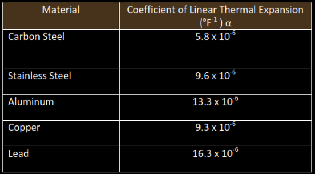
The repeated stress on the joint even though within the elastic limits can have effects like mechanical stress at the junction. The fatigue crack can appear in the heat affected zone of the parent metal with lower thermal expansion and, joint can undergo premature failure after number of thermal stress loadings.
The examples are the joints between the ferritic carbon steels and austenitic stainless steels, which often cracks at the carbon steel side. This rupture is often classified in the creep ruptures as well. The creep damage is discussed in details here. Further details on this damage mechanism can be seen from API‐RP‐571 Para 4.2.12.
4. Thermal fatigue.
Thermal fatigue is induces either by short term overheating of the cyclic thermal variation on the metals. Like mechanical fatigue the metallurgical variations take place at the thermal fatigued areas and the metal loses its yield strengths, and unexpected premature failure can take place.
Thermal fatigue is further discussed in high temperature damages in this section in Para number 4.2 of this manual and Para 4.2.9 of API‐RP‐571.