In electrical engineering, a reactor refers to a passive two-terminal electrical component that introduces inductance into a circuit. It is primarily used to control the flow of current in an electrical circuit by providing impedance. Reactors are commonly used in various applications to limit current, improve power factor, mitigate harmonics, and protect equipment.
There are two main types of reactors:
- Inductor: Reactors that primarily provide inductance to a circuit are often referred to simply as inductors. They store energy in their magnetic field when current flows through them and oppose changes in current.
- Line Reactor: This is a specific type of reactor connected in series with a power line to limit the flow of current or to provide impedance. Line reactors are often used to protect electrical equipment from voltage spikes, reduce harmonics, improve power factor, and prevent short-circuit currents.
The choice of reactor type and its parameters (inductance, rated current, etc.) depends on the specific application requirements, such as the desired level of current limiting, voltage regulation, or harmonic filtering.
What are Reactors?
Reactors, specifically 3-phase line reactors, are essential components in power systems, particularly in systems employing variable frequency drives (VFDs). Essentially, a 3-phase line reactor is an inductor wired in series between two points in a power system.

Here’s a breakdown of their functionality and structure:
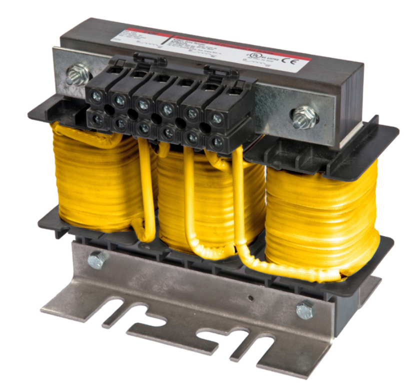
- Structure: Reactors are simple electromagnetic devices, often referred to as inductors. They typically consist of a steel core constructed from electrical-grade steel laminations, with copper wound coils on each leg of a three-phase device. Each leg and coil represent a phase of the three-phase device and are wired in series with the VFD.
- Additional Circuit Inductance: Line reactors provide additional circuit inductance, which is utilized to derive line resistance. This inductance contributes to the impedance of the system. Impedance, typically measured in ohms, is often expressed as a percentage when combined with system voltage and line current flowing through the reactor.
- Impedance and Current Flow: The percentage of impedance provided by the reactor defines the level of impedance for each rating of the line reactor. This impedance serves to slow the rate of current changes in the line. As the current through the reactor increases, the percentage of applied impedance also increases. Conversely, as the current decreases below the full load current rating of the reactor, the percentage of applied impedance decreases proportionately.
- Avoiding Oversizing: It’s crucial to avoid oversizing the line reactor for the load current of the application. Oversizing can lead to unnecessary impedance, which may not be beneficial and could potentially cause issues in the system.
Reactors, particularly 3-phase line reactors, play a crucial role in power systems by providing additional circuit inductance, which contributes to impedance and helps regulate current flow, especially in systems utilizing VFDs. Proper sizing and application of reactors are essential for optimal system performance and reliability.
VFD Protection and Harmonic Mitigation.
When applied to the input side of a variable frequency drive (VFD), a reactor serves several important functions:

- Softening Voltage Distortion: The applied impedance of the reactor helps soften and slow down incoming line voltage distortion, such as spikes and surges. This is particularly beneficial in preventing drive over-voltage faults and protecting the drive input components when line voltage deviations occur due to various factors like power factor correction capacitors switching on and off or fluctuations in high current loads.
- Mitigating Harmonic Currents: Reactors also play a role in mitigating harmonic currents drawn by the VFD. Harmonic currents can cause issues such as increased losses, overheating of equipment, and interference with other devices in the system. By introducing impedance, reactors help reduce these harmonic currents.
- Blocking Background Voltage Harmonics: In addition to mitigating harmonic currents, reactors help block background incoming line voltage harmonics. This is crucial for ensuring the smooth operation of the VFD, as excessive harmonics can interfere with the VFD’s control and cause performance issues.
- Low-Cost Solution for Protection and Harmonic Mitigation: Incorporating an input AC line reactor is considered a low-cost solution for providing protection to the VFD and mitigating harmonics. Compared to other methods of harmonic mitigation, such as active filtering or harmonic traps, adding a reactor is relatively simple and cost-effective.
The addition of an input AC line reactor to a VFD application offers significant benefits in terms of protecting the drive from voltage disturbances and harmonic issues, thereby improving the reliability and performance of the VFD system.
Load Reactor Example and Motor Protection.
Placing a reactor on the load side of a variable frequency drive (VFD) serves as an additional measure to protect motors by acting as a buffer between the drive and the motor.

Here’s how it works and why it’s beneficial:
- Buffering Effect: A standard Pulse Width Modulated (PWM) drive generates a square wave power supply to the electric motor. This waveform has sharp edges during transitions, which can lead to issues such as voltage distortion and spikes. The fast switching speed of modern output transistors in the drive results in rapid changes in voltage (dv/dt) at the edges of the waveform transitions.
- Impact on Motor: These fast waveform pulses with sharp edges can cause damage to the motor’s insulation system and shorten its service life. While inverter-duty motors are designed to tolerate such conditions to some extent, minimizing voltage distortion is crucial for optimal motor performance and longevity.
- Softening Voltage Transitions: The design inductance of the line reactor placed on the load side of the VFD helps soften the sharp edges of the voltage waveform and slow down the distortion as the voltage is supplied to the motor. By acting as a buffer, the reactor reduces the rate of change of voltage (dv/dt) experienced by the motor, thereby mitigating potential damage to the insulation system and extending the motor’s service life.
Adding a reactor on the load side of a VFD provides an additional layer of protection for motors by reducing voltage distortion and spikes, thus contributing to improved motor performance and longevity.
Line-applied reactors primarily focus on stabilizing current waveform and reducing harmonic currents drawn from the power system, load-applied reactors aim to buffer voltage stress on the motor and promote cooler operation, ultimately enhancing the reliability and performance of the VFD system.