- PURPOSE
- SCOPE
- APPLICABLE DOCUMENTS
- RESPONSIBILITY
- MANPOWER
- TOOLS & EQUIPMENT
- METHODS / PROCEDURES
- QUALITY CONTROL
- SAFETY
- PRECAUTION
- ATTACHMENTS
1.0 PURPOSE
1.1. This Procedure / method statement shall provide minimum guidelines to carry out the Field Pressure Testing of Valves in Buildings, plants and refineries. In accordance with contract scope of work and project specification.
2.0 SCOPE
2.1. This Method Statement covers the minimum requirements for Field Pressure Testing of Valves to be applied at JAZAN REFINERY and TERMINAL PROJECT Package 12-Naptha and Aromatics.
3.0 APPLICABLE DOCUMENTS
3.1. Saudi Aramco Project Specification and Standard
3.1.1 SAEP-302 Instruction for obtaining a waiver of a mandatory SaudAramco Engineering requirement.
3.1.2 S-000-3160-009 Bolt Tightening Procedure
3.1.3 SAES-A-004 General Requirements for Pressure Testing
3.1.4 G.I 2.102 Pressure Testing Safely
3.1.5 SAES-L-108 Selection of Valves
3.1.6 04-SAMSS-035 General Requirement for Valves
3.1.7 04-SAMSS-048 Valve Inspection & Testing Requirements
3.1.8 04-SAMSS-049 Inspection & Testing Requirements for API SPEC 6A 10,000 PSI Valves
3.1.9 SAES-A-007 Hydro Test Water & Lay-up Procedure
3.2 Industry Codes Standards
3.2.1 ASME B31.3 Process Piping
3.2.2 Saudi Aramco Construction Safety Manual
3.2.3 API 598 Valve Inspection and Testing
3.3 Applicable SATIP/SAIC/SATR
3.3.1 SAIC-L-2014 Inspection of bolted flange joint assembly
3.3.2 SAIC-L-2002 Review Procedure-Flange Joint Assembly & Gasket Installation.
3.3.3 SATR-L-2001 Flange Joint Tightening Inspection Report
3.3.4 SATIP-L-108-01 Valve Inspection, Testing & Installation
3.3.5 SAIC- L-2042 Pressure Testing Procedure
3.3.6 SATR-A-2001V Specification Valve Field Test
3.3.7 SAIC-A-2009 Verify Test Equipment (Safety Assessment)
3.3.8 SAIC-A-2015 Visual Inspection at Test Pressure
4.0 RESPONSIBILITY
4.1. Site Manager Responsibility for HSE shall implement, analyze and schedule all construction activities with his department to include manpower and equipment line up as well as other possible resources required for the successful implementation of the construction work activities. He shall study all aspects of work procedure as per Technical Scope of Work.
4.2. Piping Manager shall implement and review all necessary documents for the piping installation works to include, technical scope of work, specification, bill of quantities, planned milestone dates and construction procedure in support to his supervisor. He shall monitor the availability of materials in accordance with construction schedules. He shall directly report to Construction Manager.
4.3. Piping/Hydro Test Supervisor shall directly report to the Piping Manager and responsible in the implementation and control of all activities per technical Scope of work and latest approved construction drawings. He shall coordinate with other discipline to visualize possible conflicts in the drawing as well as in the schedules to provide proper options in preventing unnecessary delay & obstructions.
4.4. QC Piping Inspector shall be responsible for inspection and monitoring of the work and ensure that the works is performed and properly documented in accordance with Project requirements.
4.5. Safety Supervisor shall be responsible for monitoring safety aspects and ensuring that the work is done in accordance with JGC/DAEWOO Safety Standard Procedure. He shall discuss to the Supervisor’s the characteristics of related materials and status of work area giving reminders as an additional point to work safely.
5.0 MANPOWER
5.1. The Piping Manager shall control the overall activities of valve hydro testing works. The basic manpower under him shall consists but not limited to the following:
5.1.1. Piping Supervisor
5.1.2. Piping Foreman
5.1.3. Hydro Test Technician/Crew
5.1.4. Technician/Bolt Tightening Crew
5.1.5. Permit Receiver
5.1.6. Helpers
5.2. Safety Engineer/Officer
5.3. QC Inspector
6.0 TOOLS AND EQUIPMENT
6.1. Tools and equipment needed should be in good condition and must be checked by Piping Supervisor / Safety Officer prior to use. These includes but not limited to:
6.1.1. Tools & Equipment
6.1.1.1 Bolt Tensioning Assembly (Calibrated)
6.1.1.2 Torque Wrench (Calibrated by Third Party)
6.1.1.3 Water/Test Pump
6.1.1.4 Pressure Relief Valve
6.1.1.5 Pressure Gauge
6.1.1.6 Chain Block/Fuller
6.1.1.7 Square drive set
6.1.1.8 Hex wrench set
6.1.1.9 Set of tools as applicable
6.1.1.10 Air Compressor
7.0 METHODS/PROCEDURE
7.1 General Requirements
7.1.1 Valve Field Pressure Testing
7.1.1.1 Field testing location shall be approved by project Inspection. SAES-L-108 Para 4.7.1
7.1.1.2 If requested by the proponent, all new valves designated for isolation service (as specified by the Proponent) shall be subjected to a high pressure hydrostatic seat test prior to installation in the line. SAES-L-108 Para 4.7.2.
7.1.1.3 A low pressure pneumatic seat test at 35kPa (5 psig) shall be substituted for a high pressure hydrostatic seat test for flare system valves.
7.1.1.4 Butt weld and socket weld end valves in nominal pipe size (NPS) 2 inches and smaller are exempt from the above field testing requirements.
7.1.1.5 Test procedures, pressures, durations and leakage acceptance criteria shall be equal to those that the valves were originally purchased to. All resilient (soft) seated isolation valves shall have zero leakage.
7.1.1.6 Water quality meets the requirements of SAES-A-007. Testing intervals(maximum weekly) are establish for test water. Test water quality shall have a sulfate reducing bacteria (SRB) count of 10³ml or less as determined by Rapid Check II method SAES-A-007.
7.1.1.7 Test crew & inspectors are trained to properly follow testing procedures to eliminate water after testing and apply preservation measures such as mfg. approved lubricants & other corrosion control measures SAES-A-004.
7.1.1.8 G.I 2.102 “Pressure Testing Safely” shall be follow during pressure testing SAES-A-004 Para 5.1.
7.1.2 Valve Storage & Handling
7.1.2.1 Special care & consideration shall be taken during handling and transporting of valves.
7.1.2.2 Critical points of valves such as the valve end ports and stem shall be protected.
7.1.2.3 All valves shall comply with 04-SAMSS-035 shipment preparation requirement during transportation, handling and field storing.
7.1.2.4 Valves shall be restrained from movements during transportation to avoid damages to the main valve and its accessories.
7.1.2.5 Small size valves shall be positioned carefully to prevent any damage.
7.1.2.6 Transportation, lifting and handling of valves shall be carried out safely by appropriate equipment and trained personnel.
7.1.2.7 Hand wheels, stem, gears, actuators or any other accessories shall never be used as lifting points.
7.1.3 Receiving Inspection
7.1.3.1 Receiving inspection shall be performed prior to transfer of custody to ensure no damage has occurred during transportation and handling. A standard inspection checklist SAIC-L-2040 shall be used for full check of valves integrity.
7.1.3.2 Use SAIC-L-2040 checklist & SATR-A-2001V for valve receiving inspection.
7.1.3.3 SAIC-L-2041 Checklist & SATR-A-2001V shall be used for Storage & Preservation.
7.1.3.4 Proper segregation shall exist for CS,NACE & SS valve materials.
7.1.4 Hydrostatic Requirement
7.1.4.1 Hydrostatic test shall be carried out as per below requirements and as per inspection checklist SAIC-L-2042 Field Hydrostatic Testing of Isolation^Valves.
7.1.4.2 Test Location & Test Requirements
7.1.4.2.1 The following requirements shall be available in the test locations:
7.1.4.2.1.1 The location/shop: Shall not introduce any foreign materials that could intervene with the valve functions such as dirt/sand or other hard particles. The location shall have means of protections.
7.1.4.2.1.2 Valve fixtures: Valves shall be supported off the ground and restrained from any free movement.
7.1.4.2.1.3 Floor profile: Flooring shall be hard such as concrete floor, paving or any sort lining.
7.1.5 Testing Equipment Capability
All test are performed in accordance with documented procedures and the following, as a minimum, applies:
7.1.5.1 Test Blinds shall have the same rating and type of the valve ends. Both blinds shall be provided with pressure/vent connections.
7.1.5.2 Blind/bolts conditions must be clean and do not have signs of corrosion.
7.1.5.3 Pressure gauges are calibrated before test. The calibration interval shall not exceed one (1) month. Stickers shall be applied indicating the latest calibration date.
7.1.5.4 All pressure gauges have a range such that the test pressure is within 30 to 80% of the full range.
7.1.5.5 The relief valve of adequate capacity set to relieve at 5% above the test pressure shall be installed. The relief valve(s) shall be tested, dated and tagged within one week prior to the hydro test for new construction projects.
7.1.5.6 All the connections must have the proper pressure ratings.
7.1.5.7 A minimum of two pressure gauges are available for the test system. Their accuracy shall be within 5% of one another.
7.1.5.8 All certificates are available at site upon the Proponent representative request for verification including water chemistry report (SATR-A-2014).
7.1.5.9 Test records shall be made for each test by entries on Pressure Test Report Form 2642-ENG and the applicable Safety Instruction Sheet per SAES-A-005. *SATR-A-2001V is used.
7.1.5.10 Valve testing facility approval & start-up requirement to be comply as stated in SAIC-L-2042 Attachment 1.
7.1.6 Test Fluid
7.1.6.1 The fluid quality shall be within the acceptable criteria of API STD 6D, API STD 598 or BS 6755 Part 2 and SAES-A-007.
7.1.6.2 For shell, high pressure backseat and high pressure closure test, the test fluid shall be air, inert gas, kerosene, water or noncorrosive liquid with a viscosity not higher than that of water.
7.1.6.3 For low pressure closure test and low pressure backseat test the test fluid shall be air or inert gas.
7.1.6.4 When air or gas is used for closure, shell or backseat test the valve manufacturer shall be capable of demonstrating the adequacy of the method for leakage detection.
7.1.6.5 Water used for any test may contain water soluble oil or a rust inhibitor. When specified by the purchaser a wetting agent shall be included in the water. For testing of Austenitic Stainless steel valves, water with chloride content not exceeding 100ppm shall be used. The valve manufacturer shall be able to document the chloride content.
7.1.7 Test Required
7.1.7.1 All flange valve except check valve that are to be tested at field.
7.1.7.2 High pressure hydrostatic seat test.
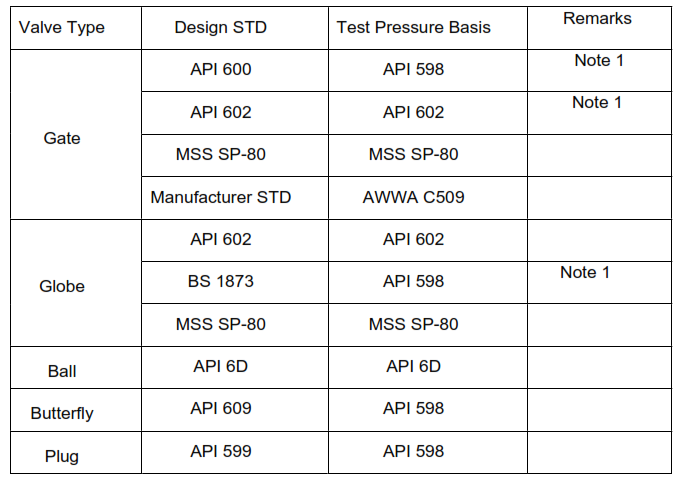
7.1.7.3 Reference industrial standard for field valve test identity test pressure, acceptance criteria etc.
7.1.8 Testing Procedure
7.1.8.1 Manufacturer instructions and guidelines shall be taken into consideration.
7.1.8.2 Backseat Test
7.1.8.2.1 The backseat test is required for all valves, except for bellows seal valves that have the backseat feature and shall be performed by applying pressure inside the assembled valve with the valve ends closed, the valve is fully open and the packing gland loose. All the packing gland shall be retightened after the backseat test.
7.1.8.3 Low Pressure Closure
7.1.8.3.1 The low pressure closure test shall be performed with the sealing surfaces clean and free from oil, grease and sealant. If necessary to prevent galling the sealing surfaces maybe coated with a film of oil that is not heavier than kerosene. This requirement does not apply to a valve that uses a lubricant as its primary seal (for example lubricated plug valves).
7.1.8.4 High pressure Closure
7.1.8.4.1 The procedure for the high pressure closure test shall be the same as the procedure for low pressure closure test except that in case of a liquid test leakage shall be detected when drops.
7.1.9 Execution Procedure
7.1.9.1 Valve test shall be conducted at Valve Testing Location.
7.1.9.2 Only personnel involved on testing are allowed to enter in the test area.
7.1.9.3 Prepare all necessary tools prior for testing.
7.1.9.4 Fill with approved test fluid through the filling point.
7.1.9.5 When the system is already filled with test fluid close all vents and start pressurizing. Pressurization shall be gradual and under control to allow time for material to strain, temperature to equalize and time for personnel to checks for leaks and weaknesses.
7.1.9.6 When pressure reaches 50% of the test pressure stop pressurization and proceed checking for leaks and weaknesses. If there is a pressure drops it indicates a leak.
7.1.9.7 If any leaks have been noticed de-pressurize and drain the test fluid, before repairing the leaks. Before draining make sure that the vents are opened before opening the drain valves. After repairing the area with leak refill and pressurize the system up to 50% of the test pressure.
7.1.9.8 After satisfactory preliminary checks for leak at 50% of strength test pressure, increase the pressure gradually by 20% and if no leak occurred during this stage, pressurization shall continue until the required test is attained.
7.1.9.9 Upon reaching 100% of the test pressure, the test pressure shall be maintained for a sufficient time according to required duration specified and inspection is to be conducted, to determine that there are no leaks and the test pump will be dis connected. Complete visual inspection.
7.1.9.10 After the test is completed and accepted, secure the acceptance signature from Inspection representative according to the approved forms for documentation.
7.1.9.11 The valve shall be completely dry by using any method such as blowing of hot or dried compressed air, controlled dew point, inert gas, sweeping by cotton cloth and or other methods to remove all test medium residuals.
7.1.9.12 Corrosion prevention, upon completion of drying process means of corrosion inhibition and lubrication shall be applied as applicable.
7.1.9.13 Method of water removal, corrosion control measures incl. lay-up & preservation (per procedure) is effectively & consistently applied in accordance with all SA & Valve Mfg. requirements after testing SAESL-108.
7.1.9.14 Upon completion of the testing, valves shall be restored to the original packing condition if installation time is not immediately after the testing as per 04-SAMSS-035 and/or SAIC-L-2041.
7.1.9.15 No valve repair shall be performed unless and until specific notification and approval from Saudi Aramco is received.
8 QUALITY CONTROL
8.1 SAACO QC personnel shall be assigned to ensure the Quality Control and Quality Assurance requirement of the project are meet.
8.2 The QC Inspector in hydro test shall coordinate with other inspector’s to conduct inspection as required in SATIP.
8.3 The QC Inspector in hydro test shall be responsible to conduct all inspections/documentations and to ensure that all applicable requirements, codes and standards are complied with.
8.4 SAACO QC Inspector in hydro test shall utilize the applicable SAIC for every activity.
8.5 Calibration shall be done as required for all machines and tools to be used in hydro test activities in accordance with schedule Q.
9 SAFETY PRECAUTION
Obtain the approval of the work permit from the concerned Representative before starting any work.
9.1 All tools shall be check and color coded..
9.2 Continuous monitoring and inspection shall be done by Piping Supervisor and Safety Supervisor and it shall be continuously implemented to detect and correct unsafe practices while performing the work activities.
9.3 Provide warning sign(“Danger High Pressure Testing” on progress in English & Arabic) and shall be posted in strategic locations. Sufficient barricade on working area and only trained & qualified personnel will be allowed in the area.
9.4 Piping Supervisor shall monitor the work activities to help and to protect the assigned workers against exposure to safety hazards. He shall ensure that Personal Protective Equipment (PPE’s) are supplied and used and comply with applicable standards. HSE will assist in giving advice.
9.5 All rigging equipment shall be in good condition and possess a valid certification from authorized certifying and inspection department, inspection and color coding shall be done in accordance with inspection guideline.
9.6 Toolbox meeting shall be conducted by Hydro Test Supervisor before the work starts so as works activities will be properly coordinated to all concerned and all safety infractions will be acted immediately.
9.7 All necessary Personal Protective equipment (PPE) shall be provided and to be worn at all times.
9.8 Housekeeping shall be maintained and working area shall be kept in a clean and tidy manner.
9.9 Job Hazard and Risk Assessment (JHRA) of this method statement shall be disseminated and explained to workers prior to start of work.