This article is about fire protection of buildings and fire protection system design guide in commercial buildings. We will see here fire protection types with brief introduction. We are going to discuss here Details and importance of fire protection system.
1. SCOPE
This article covers design, safety considerations, and mechanical equipment requirements for fire protection systems of building and loss prevention measures in plants and buildings.
2. REFERENCES
3. DEFINITIONS
Flammable Liquid
Any liquid that has flash point below 37.8 °C as determined by ASTM D 56 or ASTM D93, and vapor pressure not exceeding 2.76 bar(a) at 37.8 °C. Liquids with vapor pressure above 2.76 bar(a) at 37.8 °C are considered gases by NFPA. Flammable liquid can be further classified as follows:
a. Class IA Liquid
Flash point below 22.8 °C and boiling point below 37.8 °C
b. Class IB Liquid
Flash point below 22.8 °C and boiling point at or above 37.8 °C
c. Class IC Liquid
Flash point at or above 22.8 °C but below 37.8 °C
Combustible Liquid
Any liquid that has flash point at or above 37.8 °C, as determined by ASTM D 56 or ASTM D 93. Combustible liquid can be further classified as follows:
a. Class II Liquid
Flash point at or above 37.8 °C and below 60 °C.
b. Class IIIA Liquid
Flash point at or above 60 °C but below 93 °C.
c. Class IIIB Liquid
Flash point at or above 93 °C.
Standpipe System
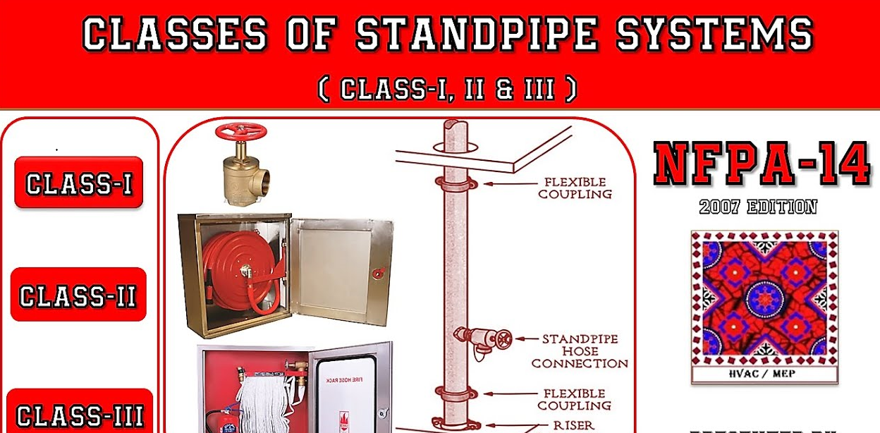
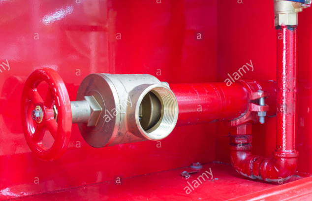
An arrangement of piping, valves, hose connections, and allied equipment installed in a building or structure, with the hose connections located in a way that water can be discharged in streams or spray patterns through attached hose and nozzles. Standpipe systems can be further classified as follows:
Class I Standpipe System
A Class I standpipe system shall provide 21/2 inches hose connections to supply water for use by fire department and those trained in handling heavy fire streams.
Class II Standpipe System
A Class II standpipe system shall provide 11/2 inches hose stations to supply water for use primarily by the building occupants or by the fire department for initial response.
c. Class III Standpipe System
A Class III standpipe system shall provide 11/2 inches hose stations to supply water for use by building occupants and 21/2 inches hose connections to supply a larger volume of water for use by fire department and those trained in handling heavy fire streams.

Water Spray System
A water spray system is an automatic or manually actuated fixed pipe system connected to a water supply and equipped with water spray nozzles designed to provide a specific water discharge and distribution over the protected area or surface. Water spray systems are usually applied to special fire hazards protection and can be used for effective fire control, extinguishment, prevention, or exposure protection.
4. BUILDING REQUIREMENTS ( Building Construction and Occupancy Types | Buildings Fire Protection )
4.1 General
4.2 High Risk Occupancy
4.3 Medium Risk – Manned Occupancy
4.4 Low Risk – Manned Occupancy
4.5 Low Risk – Unmanned Occupancy
5. BUILDING TYPES
5.1 Maintenance Shop Building ( Fire Protection Requirements of Maintenance Shop Building ).
5.2 Control Building ( Fire Protection Requirements of Control Building ).
5.3 Warehouse ( Fire Protection Requirements of Control Building ).
5.4 Compound Building ( Fire Alarm & Detection Requirements of Compound Building ).
5.5 Substation Building ( Fire Alarm & Fire Protection of Substation Building ).
5.6 Gate House
5.7 Office and Training Building ( Fire Alarm & Fire Protection of Office and Training Building ).
5.8 Sunshade Building (Fire Alarm & Fire Protection of Sunshade Building).
5.9 Operator Shelter Building.
5.10 Laboratories (Fire Alarm & Fire Protection of Laboratories).
5.11 Hazardous Material Handling Building (Fire Alarm & Fire Protection of Hazardous Material Handling Building).
6. FIRE AND GAS DETECTION SYSTEMS ( Fire and Gas Detection Systems | Fire Protective Signaling Systems )
6.1 Fire and Gas Detection Panels.
6.2 Fire Alarm and Detection Panels.
6.3 Fire Suppression System Control Panels.
6.4 Addressable Analog Smoke Detectors.
6.5 Addressable Analog Heat Detectors.
6.6 Addressable Manual Fire Alarm Station.
6.7 Conventional Manual Fire Alarm Station.
6.8 UV/IR Flame Detector.
6.9 R/IR/IR Flame Detector.
6.10 R Combustible Gas Sensor.
7. FIRE SUPPRESSION SYSTEMS ( Fire Suppression Equipment Provision for Generic Indoors Location )
7.1 CO2 Extinguishing Systems
7.2 Clean Agent Extinguishing Systems
8. FIRE PROTECTION SYSTEMS ( Automatic Sprinkler systems Design | Installation | Materials )
8.1 Sprinkler System
8.2 Water Spray System
8.3 Foam System
8.4 Water Mist System
9. HOSE REEL STATION
- For protection of Hazardous Material Handling Building, hose reel equipped with foam delivering capacity may be used. See F-02-E-01 (Fire Protection Systems) Section 12 for details.
- For protection of other buildings, hose reels shall be provided. Hose reels without foam capacity shall be connected to the standpipe systems (indoor hydrants). Requirements of hose reels without foam capacity are described as follows:
- Valve: A 2 1/2 in (6.4 cm) control and regulating valve for fir service end-of-pipe application shall be provided. This valve shall be able to regulate the inlet pressure up to 27.5 bar(g) (400 psig) and equipped with an indicator to show whether valve is open or closed.
- Coupling: A 1 1/2 inch (3.8 cm) single lug coupling shall be provided to allow attachment of hose to nipple which connects the control valve.
- Hose: One 1 1/2 in, 22.8 m (75 feet), polyflex hose with 100% synthetic jacket and 100% synthetic lining shall be provided. Longer (30.4 m) or shorter (15.2 m) length of hose can also be used at the locations where it serves better. Minimum 20.6 bar(g) (300 psig) acceptance test pressure rating shall be certified.
- Nozzle: One 1 1/2 in adjustable fog to straight stream nozzle shall be provided.
- Semi-Automatic Hose Rack: This hose rack shall provide storage for folded hose and nozzle.
HOSE REEL STATION
10. FIRE HOSE CABINET
Where semi-automatic hose racks are not provided, a fold hose cabinet installed in building wall shall be provided. The stored fire hose shall connect to the standpipe system.

11. STANDPIPE SYSTEM (INDOOR HYDRANT)
Standpipe systems are defined in Section above of this article. Class II system shall be used and sized for a minimum flow of 380 lpm at 6.9 bar(g) inlet pressure. The number of hose reel stations for Class II service in each building and each section of a building divided by firewalls shall be such that all portions of each story of the building are within 9 m of the nozzle attached to the full stretch of the hose.
12. FIRE EXTINGUISHERS
Arrangement : The following shall be provided:
7.7 kg ammonium phosphate “ABC” dry chemical extinguisher.
The extinguishers shall be located based on a guide of maximum travel distance of 15 m to every equipment item to be protected.
6.9 kg CO2 extinguisher.
The CO2 extinguisher shall be located based on a guide of a maximum travel distance of 9 m from electrical equipment to be protected.
45.3 kg CO2 wheeled extinguisher.
These extinguishers shall be located in or near electrical substations, and/or switchgear rooms operating with voltages greater than 600v and near emergency diesel generators.
Fire Extinguisher Installation
Portable fire extinguishers shall be installed in the following manner:
-
- Wall-mounted fire extinguishers shall be installed on a suitable bracket.
- Wheeled extinguishers shall be freestanding.
- Free standing hand portable extinguishers shall be provided with a pan and stand.
13. BREATHING APPARATUS
- Sufficient self-contained breathing apparatus (SCBA) shall be stored in the fire station and control room for use during an emergency. They shall be recharged on site using a compressor dedicated to supplying breathing quality air. The air intake for the compressor shall be sited in a safe location and provision shall be made for periodic checking of the quality of the compressed air.
- SCBA shall have the following features:
a. NIOSH (National Institute for Occupational Safety and Health) approved.
b. 30 minutes rated duration.
c. Facemask, regulator, carrying case provided.
14. TESTING OF FIRE PROTECTION SYSTEM
Contractor is responsible for performing all applicable acceptance tests as required by the reference standards. This includes flushing, hydrostatic pressure, and discharge tests. All authorized representatives from Owner, Company, and Contractor shall attend the final acceptance test to ensure that all the criteria have been met.
In addition to the standard hydrostatic test, an air leakage test shall be conducted on the hydraulic pilot piping according to the following criteria whichever is selected.
Four (4) hours at 5.5 bar(g) with air. A leak rate no greater than 0.14 bar(g) for four hours is acceptable.
Twenty four (24) hours at 2.8 bar(g) with air. A leak rate no greater than 0.1 bar(g) for twenty fours is acceptable.
15. CONTRACTOR REQUIREMENTS
- Contractor shall comply with all the requirements stated in the design and reference standards.
- All items of equipment supplied by the Contractor shall be tested and inspected for conformance to the specified standards.
- Data, drawings, and other documentation requirements shall be in accordance with the Supplier Data Requirements List.
- The Contractor shall provide recommended equipment spare parts specified in the purchasing documents.
