Flight and Navigation Instruments
1. Airspeed indicator.
The airspeed indicator is a vital component of an aircraft’s instrumentation, providing pilots with crucial information about the aircraft’s speed relative to the surrounding air. Operating on the principle of pressure differentials, this instrument measures the dynamic pressure of the airflow entering the aircraft’s pitot tube, which is oriented to face forward into the oncoming air. As the aircraft accelerates, the dynamic pressure increases, reflecting the higher velocity of the airflow.
In conjunction with measuring dynamic pressure, the airspeed indicator also accounts for static pressure, which represents the atmospheric pressure outside the aircraft. This static pressure remains relatively constant regardless of the aircraft’s speed. By comparing the dynamic and static pressures, the airspeed indicator calculates the indicated airspeed (IAS), which is displayed to the pilot on the instrument panel.
However, the indicated airspeed must undergo corrections to provide accurate information. One important correction factor is air density, which varies with altitude and temperature changes. Barometric and temperature data are used to adjust the indicated airspeed to obtain the true airspeed, accounting for these variations in air density.
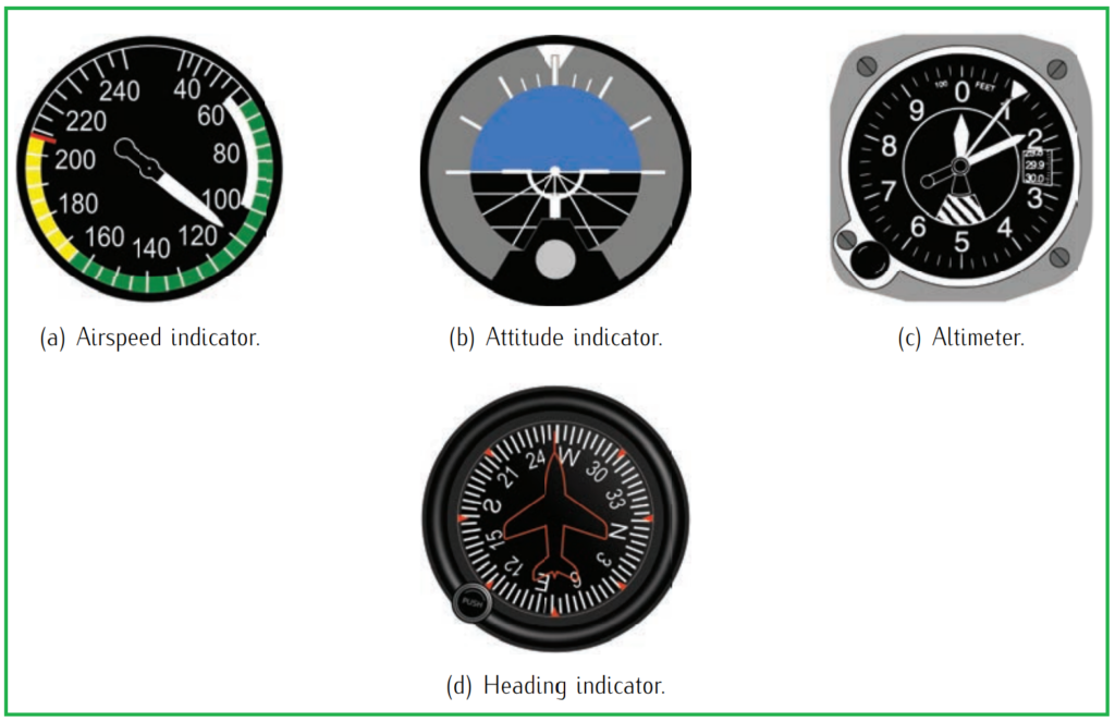
2. Attitude indicator (artificial horizon).
The attitude indicator, commonly referred to as the artificial horizon, is a critical instrument in an aircraft’s cockpit, offering pilots essential information about the aircraft’s orientation relative to the horizon. Essentially, it provides a visual representation of the aircraft’s attitude, including details such as the levelness of the wings and the pitch of the aircraft’s nose in relation to the horizon.
Pilots rely on the attitude indicator to maintain proper aircraft control, especially during periods of reduced visibility or when flying in conditions where visual references are limited, such as during night flights or in adverse weather. By observing the artificial horizon, pilots can ensure that the aircraft maintains the desired orientation and attitude for safe and precise flight.
The attitude indicator operates using gyroscopic principles, with gyroscopes inside the instrument maintaining a stable reference point despite the aircraft’s movements. As the aircraft pitches, rolls, or yaws, the gyroscopic mechanism enables the attitude indicator to accurately depict these changes in orientation, providing real-time feedback to the pilot.
3. Altimeter.
The altimeter is a crucial instrument in an aircraft’s cockpit, providing pilots with vital information about the aircraft’s altitude above a designated reference point. Typically measured in feet, the altimeter displays the aircraft’s elevation relative to various reference points, such as sea level, the destination airport, or a standard atmospheric pressure level (known as the 101325 isobar).
Operating on the principle of barometric pressure, the altimeter utilizes aneroid capsules housed within the instrument to detect changes in atmospheric pressure. These capsules, containing a gas, respond to fluctuations in air pressure as the aircraft ascends or descends. When the aircraft climbs, the decrease in atmospheric pressure causes the gas-filled capsules to expand, signaling an increase in altitude on the altimeter display. Conversely, during descent, the higher atmospheric pressure compresses the capsules, indicating a decrease in altitude on the instrument.
The altimeter’s accuracy relies on precise calibration and adjustments for factors such as temperature variations and barometric pressure settings. Pilots can select different barometric settings, such as QNE, QNH, or QFE, to align the altimeter’s reference point with the desired altitude measurement standard.
4. Heading indicator (directional gyro).
The heading indicator, often referred to as the directional gyro, plays an important role in providing pilots with accurate information about the aircraft’s heading relative to magnetic north. Operating on the principle of a gyroscope, this instrument offers essential guidance for maintaining course direction during flight.
Unlike magnetic compasses, which can be affected by external magnetic fields and require frequent recalibration, the heading indicator remains reliable and stable throughout the flight. This reliability is achieved through the use of a gyroscope—a spinning rotor with a high degree of inertia—that maintains a consistent orientation in space, unaffected by external forces.
The directional gyro’s gyroscopic mechanism ensures that the instrument’s display accurately reflects the aircraft’s heading, providing pilots with a constant reference point regardless of magnetic variations or external influences. As the aircraft changes its heading, the gyroscopic mechanism inside the instrument maintains its alignment with the magnetic north, allowing pilots to monitor changes in direction with precision.
5. Magnetic compass.
The magnetic compass is an essential instrument in aircraft navigation, providing pilots with the aircraft’s heading relative to magnetic north. While it is highly reliable during steady level flight, its accuracy may be compromised during dynamic flight conditions such as turning, climbing, descending, or accelerating.
One of the limitations of the magnetic compass is its susceptibility to errors caused by the inclination of the Earth’s magnetic field. This can lead to inaccuracies in heading readings, particularly when the aircraft is subjected to changes in altitude or acceleration. As a result, relying solely on the magnetic compass for precise navigation during these maneuvers may not be advisable.
To address the limitations of the magnetic compass, pilots often use the heading indicator as a more reliable alternative. The heading indicator, based on gyroscopic principles, provides accurate and stable heading information unaffected by changes in flight dynamics or magnetic field variations. It offers a consistent reference point for pilots to maintain course direction and navigate effectively, particularly during maneuvers where the magnetic compass may be less reliable.
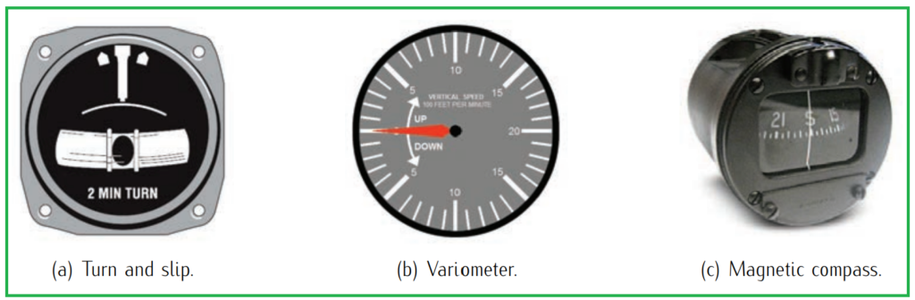
6. Turn indicator (turn and slip).
The turn indicator, also referred to as the turn and slip indicator, is a vital instrument in aircraft navigation that provides pilots with essential information about the direction and quality of turns during flight. It serves two main functions: indicating the direction of turn and displaying the rate of turn.
Firstly, the turn indicator shows the direction of turn by indicating the rate at which the aircraft’s heading is changing. This helps pilots maintain awareness of whether they are turning left or right and at what speed, enabling them to make precise adjustments to their flight path as needed.
Additionally, the turn indicator includes an internally mounted inclinometer, often represented as a balance indicator or a ball. This component serves to indicate the quality of the turn by showing whether the turn is correctly coordinated or uncoordinated. In a coordinated turn, the ball remains centered within the inclinometer, indicating that the aircraft is maintaining proper balance and control throughout the maneuver.
7. Vertical speed indicator (variometer).
The vertical speed indicator, also known as the variometer, is a crucial instrument in aircraft navigation, providing pilots with essential information about the rate of climb or descent during flight. This instrument typically displays the vertical speed in units of feet per minute (ft/min) and operates by sensing changes in air pressure.
By measuring the rate at which air pressure changes as the aircraft ascends or descends, the variometer accurately indicates whether the aircraft is climbing, descending, or maintaining a level flight path. Pilots rely on this information to adjust their altitude as needed, ensuring smooth and controlled changes in elevation throughout the flight.
In addition to displaying vertical speed, the variometer may also include indicators for exterior air temperature and a clock. These additional features provide pilots with valuable supplementary information, such as ambient temperature conditions and time, which are important for flight planning, navigation, and situational awareness.
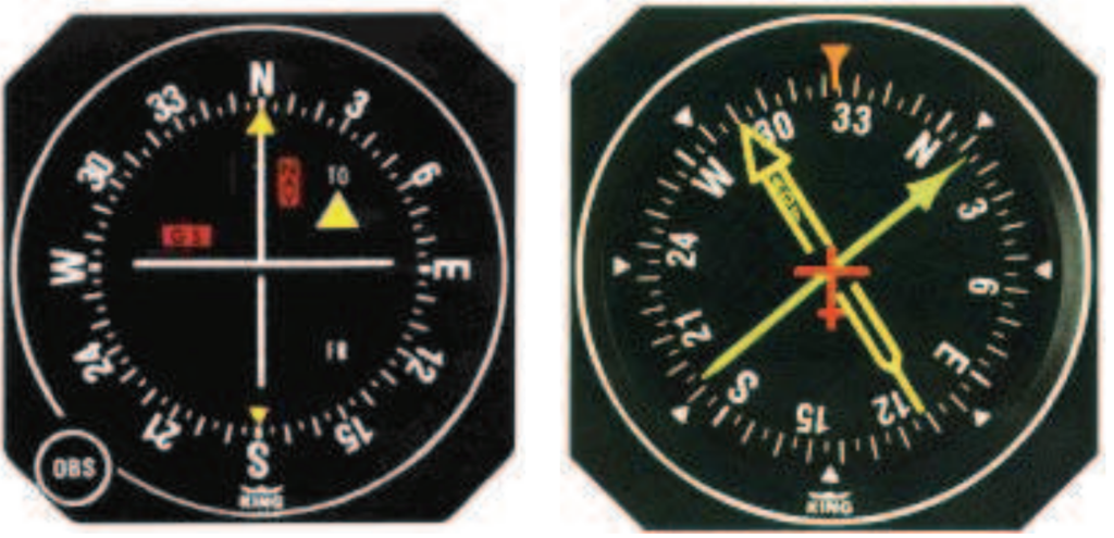
8. Additional panel instruments.
In addition to the essential flight instruments, many aircraft are equipped with additional panel instruments to enhance navigation and situational awareness. These instruments provide pilots with valuable data for precise navigation and approach procedures. Some of these additional instruments include:
- Course Deviation Indicator (CDI): The CDI is a navigation instrument used to determine an aircraft’s lateral position relative to a desired track, often provided by navigation aids such as VOR or ILS. It helps pilots maintain course alignment by displaying deviations from the intended track. In some configurations, the CDI may be integrated with the heading indicator to provide lateral navigation information on a single display known as a horizontal situation indicator (HSI).
- Radio Magnetic Indicator (RMI): The RMI is commonly paired with an Automatic Direction Finder (ADF), which provides bearing information to a tuned Non-Directional Beacon (NDB). Unlike basic ADF displays, an RMI typically features two needles that represent bearings from two separate ADF receivers. This allows pilots to triangulate their position by intercepting and comparing bearings from different sources.
- Instrument Landing System (ILS): The ILS is a crucial system for aircraft during final approach and landing, especially in adverse weather conditions. The on-board ILS equipment provides pilots with guidance cues for both vertical and lateral navigation to align the aircraft with the runway axis and maintain the correct glide path. It consists of localizer and glide slope components that provide precise guidance for landing in low visibility conditions, ensuring safe and accurate approaches.
These additional panel instruments complement the primary flight instruments, offering pilots comprehensive navigation and approach capabilities. By utilizing these instruments effectively, pilots can navigate with confidence and precision, even in challenging weather conditions or complex airspace environments.