This article is about Flow Switch and Water Valve Position Switches Selection Criteria and Installation of Fire Alarm System as per International Codes and standards for Commercial Buildings, Plants and Refinery Projects.
Flow Switch and Water Valve Position Switches Selection Criteria and Installation
- Fire Alarm System Certification- Fire Alarm System shall be certified by the manufacturer that the designs and materials used in the installation of its Sprinkler System is meeting NFPA 13 Installation of Sprinkler Systems.
- Fire Alarm System Certification- Fire Alarm System shall be certified by the manufacturer that the designs and materials used in its installation is meeting the following standards:
NFPA 13 Installation of Sprinkler Systems (Automatic Sprinkler Systems Handbook)
NFPA 13R Standard for the Installation of Sprinkler Systems in Residential Occupancies up to and Including Four Stories in Height
NFPA 14 Standard for the Installation of Standpipe and Hose Systems
NFPA 70 National Electrical Code (NEC)” - As Designed – Fire Alarm System and accessories shall be in accordance with the Saudi Aramco-approved project-specific design drawings, diagrams, schedules, lists, databases, and associated design documents.
- Identification – Fire Alarm materials shall be identified by using tags, stamps, color coding, stencils or labels. The location and method of identification shall not affect the function or quality of the materials.
- New and Unused – Fire Alarm materials shall be new and unused.
- Free of Damage – Fire Alarm materials shall be free of damage. All Incoming material shall be visually inspected for damage and conformance to all applicable inspection releases with Material Test Report (MTR).
- QC Before Installation – Fire Alarm materials shall conform to all applicable requirements, standards, and specifications prior to release to be used as part of the work.
- Traceability – Fire Alarm materials [ Fire Alarm Systems, smoke and heat detectors] shall be traceable from the manufacturer and supplier through delivery, storage, fabrication, erection, installation, repair, modification and use.
- Control buildings, PIBs, SIHs, UPS rooms, and communications buildings/rooms shall have a fire detection and alarm system. Other buildings in the scope of this Standard shall have a fire detection and alarm system if required by SAES-M-100.
Water Flow Switch Material Selection
The number of water flow switches permitted to be connected to actuate a single transmitter shall not exceed five switches (NFPA 72 sec 8.6.3.3.3.4)
- Initiating Device Circuit with Parallel Waterflow Alarm Switches and a Series Supervisory Valve Switch, Which No Longer Meets the Requirements of NFPA 72. An open fault in the circuit wiring or operation of the valve switch should cause a trouble signal. See Figure C.2.15. (Attachment 1). [NFPA 72 sec C.2.15]
- The provisions of Section 5.11 shall apply to devices that initiate an alarm indicating a flow of water in a sprinkler system. (NFPA 72 sec 5.11.1)
- Activation of the initiating device shall occur within 90 seconds of water flow at the alarm-initiating device when flow occurs that is equal to or greater than that from a single sprinkler of the smallest orifice size installed in the system. (NFPA 72 sec 5.11.2)
- Movement of water due to waste, surges, or variable pressure shall not initiate an alarm signal. (NFPA 72 sec 5.11.3)
- Piping between the sprinkler system and a pressure actuated alarm-initiating device should be galvanized or of nonferrous metal or other approved corrosion-resistant material of not less than 9.5 mm (3/8 in.) nominal pipe size. (NFPA 72 sec A.5.11.1)
- The water flow device should be field adjusted so that an alarm is initiated no more than 90 seconds after a sustained flow of at least 40 L/min (10 gpm). (NFPA 72 sec A.5.11.2)
- Features that should be investigated to minimize alarm response time include the following:
(1) Elimination of trapped air in the sprinkler system piping
(2) Use of an excess pressure pump
(3) Use of pressure drop alarm-initiating devices
(4) A combination thereof
(NFPA 72 sec. A.5.11.2) - Care should be used when choosing water flow alarm initiating devices for hydraulically calculated looped systems and those systems using small orifice sprinklers. Such systems might incorporate a single point flow of significantly less than 40 L/min (10 gpm). In such cases, additional water flow alarm initiating devices or the use of pressure drop-type water flow alarm-initiating devices might be necessary. (NFPA 72 sec A 5.11.2)
- Care should be used when choosing water flow alarm initiating devices for sprinkler systems that use on-off sprinklers to ensure that an alarm is initiated in the event of a water flow condition. On-off sprinklers open at a predetermined temperature and close when the temperature reaches a predetermined lower temperature. With certain types of fires, water-flow might occur in a series of short bursts of a duration of 10 seconds to 30 seconds each. An alarm-initiating device with retard might not detect water flow under these conditions. An excess pressure system or a system that operates on pressure drop should be considered to facilitate waterflow detection on sprinkler systems that use on–off sprinklers. (NFPA 72 sec A 5.11.2)
- Excess pressure systems can be used with or without alarm valves. The following is a description of one type of excess pressure system with an alarm valve. (NFPA 72 sec A.5.11.2)
An excess pressure system with an alarm valve consists of an excess pressure pump with pressure switches to control the operation of the pump. The inlet of the pump is connected to the supply side of the alarm valve, and the outlet is connected to the sprinkler system. The pump control pressure switch is of the differential type, maintaining the sprinkler system pressure above the main pressure by a constant amount. (NFPA 72 sec A.5.11.2) - Another switch monitors low sprinkler system pressure to initiate a supervisory signal in the event of a failure of the pump or other malfunction. An additional pressure switch can be used to stop pump operation in the event of a deficiency in water supply. (NFPA 72 sec A.5.11.2)
- Another pressure switch is connected to the alarm outlet of the alarm valve to initiate a water flow alarm signal when water flow exists. This type of system also inherently prevents false alarms due to water surges. The sprinkler retard chamber should be eliminated to enhance the detection capability of the system for short duration flows. (NFPA 72 sec A.5.11.2)
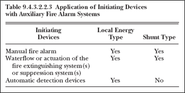
The application of the two types of auxiliary fire alarm systems shall be limited to the initiating devices specified in Table 9.4.3.2.2.3 (See attachment 2). [NFPA 72 sec 9.4.3.2.2.3]
If pressure or water flow switches are used to shut down elevator power immediately upon or prior to the discharge of water from sprinklers, the use of devices with time delay switches or time-delay capability shall not be permitted. (NFPA 72 sec 6.16.4.3) - Care should be taken to ensure that elevator power cannot be interrupted due to water pressure surges in the sprinkler system. The intent of the Code is to ensure that the switch and the system as a whole do not have the capability of introducing a time delay into the sequence. (NFPA 72 sec A.6.16.4.3)
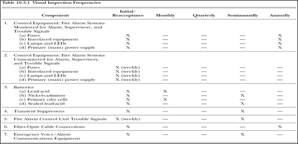
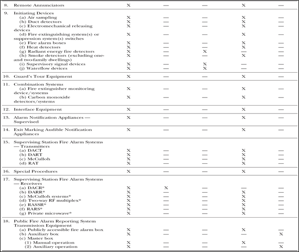
- Visual inspections shall be performed in accordance with the schedules in Table 10.3.1 (See attachment 3) or more often if required by the authority having jurisdiction. Exception: Devices or equipment that is inaccessible for safety considerations (e.g., continuous process operations, energized electrical equipment, radiation, and excessive height) shall be inspected during scheduled shutdowns if approved by the authority having jurisdiction. Extended interuals shall not exceed 18 months. (NFPA 72 sec10.3.1)
- Display Rate. To facilitate the prompt receipt of fire alarm signals from systems handling other types of signals that are able to produce multiple simultaneous status changes, the requirements of either of the following shall be met:
(1) The system shall record simultaneous status changes at a rate not slower than either a quantity of 50 or 10 percent of the total number of initiating device circuits connected, within 90 seconds, whichever number is smaller, without loss of any signal.
(2) The system shall either display or record fire alarm signals at a rate not slower than one every 10 seconds, regardless of the rate or number of status changes occurring, without loss of any signals.
Exception: If fire alarm, water flow alarm, and sprinkler supervisory signals and their associated trouble signals are the only signals processed by the system, the rate of recording shall not be slower than one signal every 30 seconds. (NFPA 72 sec 8.4.4.4)” - Alarm Signal Initiation – Sprinkler Systems: Where required to be electronically monitored, waterflow alarm-initiating devices shall be connected to a dedicated function fire alarm control unit designated as
- sprinkler waterflow and supervisory system,” and permanently identified on the control unit and record drawings.
Exception: Where waterflow alarm-initiating devices are connected to a building fire alarm system, a dedicated function fire alarm control unit shall not be required. (NFPA 72 sec 6.8.5.5.1)” - The number of waterflow alarm–initiating devices permitted to be connected to a single initiating device circuit shall not exceed five. (NFPA 72 sec 6.8.5.5.2)
- Fire alarm systems and other systems and equipment that are associated with fire alarm systems and accessory equipment shall be tested according to Table 10.4.2.2. (NFPA 72 sec 10.4.2.2)
Water Valve Position Switch Material Selection
- Control Valve Supervisory Signal-Initiating Device: Two separate and distinct signals shall be initiated:
-one indicating movement of the valve from its normal position (off-normal)
-and the other indicating restoration of the valve to its normal position. (NFPA 72 sec 5.15.1.1)” - The off-normal signal shall be initiated during the first two revolutions of the hand wheel or during one-fifth of the travel distance of the valve control apparatus from its normal position (NFPA 72 sec 5.15.1.2)
- The off-normal signal shall not be restored at any valve position except normal. (NFPA 72 sec 5.15.1.3)
- An initiating device for supervising the position of a control valve shall not interfere with the operation of the valve, obstruct the view of its indicator, or prevent access for valve maintenance. (NFPA 72 sec 5.15.1.4)
- A valve supervisory, low-pressure switch or other device intended to cause a supervisory signal when actuated should not be connected in series with the end-of-line supervisory device of initiating device circuits, unless a distinctive signal, different from a trouble signal, is indicated. (NFPA 72 sec A.4.4.3.6.2(2))
Water Flow Switch and Water Valve Position Switch – Installation
- NEC Article 760 covers the installation of wiring and equipment of fire alarm systems including all circuits controlled and powered by the fire alarm system. (NEC sec 760.1).
- NEC Article 760 FPN No.1: Fire alarm systems include fire detection and alarm notification, guard’s tour, sprinkler water flow, and sprinkler supervisory systems. Circuits controlled and powered by the fire alarm system include circuits for the control of building systems safety functions, elevator capture, elevator shutdown, door release, smoke doors and damper control, fire doors and damper control and fan shutdown, but only where these circuits are powered by and controlled by the fire alarm system. For further information on the installation and monitoring for integrity requirements for fire alarm systems, refer to the NFPA 72®-1999, National Fire Alarm Code®. (NEC sec 760.1)
- Mechanical Execution of Work: Fire alarm circuits shall be installed in a neat workmanlike manner. Cables and conductors installed exposed on the surface of ceilings and sidewalls shall be supported by the building structure in such a manner that the cable will not be damaged by normal building use. Such cables shall be supported by straps, staples, cable ties, hangers, or similar fittings designed and installed so as not to damage the cable. The installation shall also comply with 300.4(D). [NEC sec 760.24]
- System Installer: Installation personnel shall be qualified or shall be supervised by persons who are qualified in the installation, inspection, and testing of fire alarm systems. Evidence of qualifications or certification shall be provided when requested by the authority having jurisdiction. Qualified personnel shall include, but not be limited to, one or more of the following:
(1) Personnel who are factory trained and certified for fire alarm system installation of the specific type and brand of system being installed
(2) Personnel who are certified by a nationally recognized fire alarm certification organization acceptable to the authority having jurisdiction
(3) Personnel who are registered, licensed, or certified by a state or local authority (NFPA 72 sec 4.3.3) - Devices and appliances shall be located and mounted so that accidental operation or failure is not caused by vibration or jarring. (NFPA 72 sec 4.4.4.2.2)
- All apparatus requiring rewinding or resetting to maintain normal operation shall be restored to normal as promptly as possible after each alarm and kept in normal condition for operation. (NFPA 72 sec 4.4.4.2.3)
- Fire Alarm including Water flow Switch and Valves Positions installed in Corrosive, Damp, or Wet Locations. Shall meet the requirement of NEC sections 110.11, 300.6, and 310.9 where installed in corrosive, damp, or wet locations. (NEC sec 760.3(D).
- Hazardous (Classified) Locations. Installations of fire Alarm equipment in hazardous (classified) locations shall also comply with the appropriate provisions for hazardous (classified) locations in other applicable articles of this Code. (NEC sec. 720.3)
- Pipe or tubing for sprinkler systems shall be in accordance with SAES-S-050. (SAES-M-100 sec 903.1)
- Fittings and valves used in sprinkler systems shall be in accordance with SAES-S-050. (SAES-M-100 sec 903.1)
- Indicating Control Valves. An indicating control valve shall be installed in the connection to pressure-type contactors or water motor operated alarm devices (NFPA 13 sec 8.16.1.4.1)
- Such valves shall be sealed, locked, or electrically supervised in the open position (NFPA 13 sec 8.16.1.4.2)
- The control valve for the retarding chamber on alarm check valves shall be accepted as complying with the requirements of 8.16.1.4. connection (NFPA 13 sec 8.16.1.4.3)
- Each sprinkler system shall be provided with a listed indicating valve in an accessible location, so located as to control all automatic sources of water supply. NFPA 13sec 8.15.1.1.1.1)
- At least one listed indicating valve shall be installed in each source of water supply. (NFPA 13 sec 8.15.1.1.1.2)
- The requirements of 8.15.1.1.1.2 shall not apply to the fire department connection, and there shall be no shutoff valve in the fire department connection. (NFPA 13 sec 8.15.1.1.1.3)
- Where there is more than one source of water supply, a check valve shall be installed in each connection (NFPA 72 sec 8.15.1.1.3.1)
- Check valves shall be installed in a vertical or horizontal position in accordance with their listing. (NFPA 13 sec. 8.15.1.1.3.4)
International Standard and Codes for Flow Switch and Water Valve Position Switches
3. NFPA 13 – Standard for the Installation of Sprinkler Systems 2007 Edition
4. NFPA 70 – National Electrical Code (NEC), 2008 Edition
5. NFPA 72 – National Fire Alarm Code, 2007 Edition
6. SAES-P-104 – Wiring Methods and Materials, 13 January, 2008
7. SAES-B-014 – Safety Requirements for Plant and Operations Support Buildings, 29 February 2004
8. SAES-M-100 – Saudi Aramco Building Code, 09 October, 2006
9. ANSI/UL 10B – Fire Tests of Door Assemblies, Tenth Edition, Dated February 07, 2008
10. UL 268 – SMOKE DETECTORS FOR FIRE ALARM SIGNALING SYSTEMS – August 14, 2009
1. Attachment 1: NFPA 72 Table 5.6.2.1.1
2. Attachment 2: UL 268 Table 9.3
3. Attachment 3: NFPA 72 Table 10.3.1


