Globe valves are an essential component in various industries, playing a critical role in controlling fluid flow within pipelines and systems. Their distinctive design and functional characteristics make them suitable for a wide range of applications, from simple on-off control to precise flow modulation. In this comprehensive article, we delve into the technical aspects of globe valves, exploring their construction, working principles, types, applications, advantages, and considerations for optimal usage.
What is Globe Valve?
The design of a globe valve allows for gradual opening and closing, reducing the risk of water hammer and pressure surges. This gradual modulation of flow is particularly important in systems where sudden changes in flow could lead to equipment damage or operational issues.
Globe valves are also known for their ability to provide a tight shut-off, ensuring minimal leakage when the valve is closed. This sealing characteristic makes them ideal for applications where leakage prevention is crucial, such as in hazardous or toxic fluid handling.
The throttling capability of globe valves makes them suitable for controlling flow rates and pressures in various systems. They are commonly used in control applications where precise adjustment of flow is required, such as in cooling systems, steam pipelines, and chemical processing plants.
Globe valves are widely recognized for their ability to regulate fluid flow by modulating the flow rate through a circular orifice. Their distinct shape, resembling a globe, gives them their name. The design allows for precise control of flow and pressure, making globe valves a preferred choice in applications where throttling or regulation is essential.
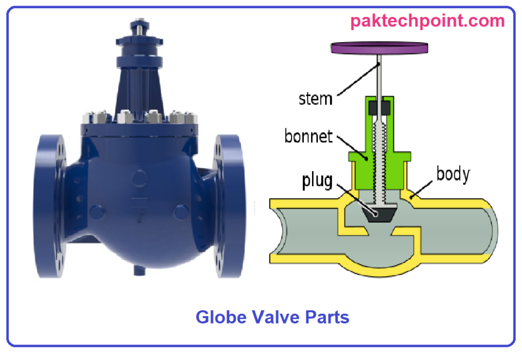
Globe Valve Construction and Parts:
Globe valves consist of several key components that work in synergy to control fluid flow. The body houses the internal components and provides the necessary connection points for the pipeline. The bonnet encloses the valve internals and provides a seal to prevent leakage.
The stem connects the actuator to the disc or plug, which modulates the flow. The seat creates a seal against the disc, ensuring a tight shut-off. Actuators, such as handwheels, gear operators, or electric motors, facilitate valve operation. Packing and gland mechanisms prevent leakage around the stem. Flanges and connections allow the valve to be installed within a pipeline system.
Each component of a globe valve plays a crucial role in its overall functionality. Let’s delve into the details of each part to understand how they contribute to the operation of this essential valve:
- Body:
The body of a globe valve serves as the primary structure that contains all the internal components. It is typically a cylindrical or spherical shell that provides a pathway for fluid to flow. The design and material of the body depend on the specific application and the type of fluid being controlled. - Bonnet:
The bonnet is a cover that is attached to the top of the valve body. It provides protection and support for the valve stem and other internal parts. The bonnet is usually bolted or threaded onto the body, ensuring a secure closure that prevents leakage. - Stem:
The stem is a crucial component that connects the actuator to the disc or plug inside the valve. When the actuator is operated, it moves the stem, which in turn moves the disc to control the flow of the fluid. The stem must be durable and resistant to corrosion to ensure smooth and reliable operation. - Disc or Plug:
The disc or plug is the component that controls the flow of the fluid by blocking or allowing it to pass through the valve. When the valve is closed, the disc is pressed against the seat to create a tight seal and prevent the flow of fluid. When the valve is open, the disc is lifted away from the seat to allow fluid to pass through. - Seat:
The seat is the sealing surface where the disc makes contact to shut off the flow of fluid. It ensures a tight seal to prevent leakage when the valve is closed. The shape and material of the seat can vary based on the application and the type of fluid being controlled. - Actuator:
The actuator is the mechanism that controls the movement of the stem and, consequently, the disc or plug. Actuators can be manual, such as handwheels or levers, or automated, such as electric, pneumatic, or hydraulic actuators. Automated actuators allow for precise control and remote operation of the valve. - Packing and Gland:
The packing and gland provide a seal around the stem to prevent leakage along its length. The packing material is compressed by the gland, creating a secure seal that prevents fluid from escaping. Proper packing and gland maintenance are essential to ensure the longevity and efficiency of the valve. - Flanges and Connections:
Flanges are used to connect the valve to the pipeline or other components. They provide a secure attachment point and facilitate the installation and removal of the valve. The type of flange used depends on the specific application and the requirements of the system.
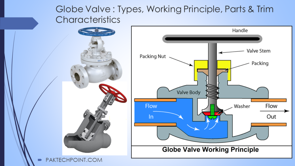
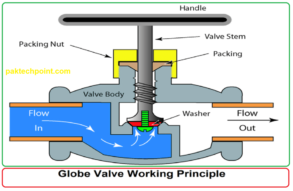
Globe Valve Working Principles:
The working principle of a globe valve is based on the up-and-down movement of the disc or plug against the seat. This movement controls the flow of fluid through the valve. When the disc is lifted, the flow passage opens, allowing fluid to pass through. As the disc is lowered, the flow passage is restricted, reducing the flow rate. This modulating action allows for precise control of fluid flow and pressure.
The flow control mechanism, operation modes, valve closure, and leakage are critical aspects of valve functionality that influence their performance and application. Let’s explore these aspects in detail:
Flow Control Mechanism:
Valves, including globe valves, employ different mechanisms to control the flow of fluids within pipelines. The primary objective is to manage the rate and direction of fluid flow according to the system’s requirements. Globe valves utilize a disc or plug that can be positioned to obstruct or allow the passage of fluid. By adjusting the position of the disc through the actuator, the flow rate can be regulated effectively.
Operation Modes: On-Off and Throttling:
Valves are employed in various operation modes based on the intended purpose. The two primary operation modes are on-off and throttling.
- On-Off Mode:
In this mode, the valve serves as a simple on-off switch for fluid flow. It is used to either allow the fluid to pass through (valve open) or block its passage (valve closed). On-off valves, including globe valves, are commonly used in applications where the fluid flow needs to be completely shut off or allowed. - Throttling Mode:
Throttling, also known as modulation, involves controlling the flow rate of the fluid by partially opening or closing the valve. Throttling valves, like globe valves, are employed when precise flow control is required, allowing for gradual adjustments in the fluid flow rate.
Valve Closure and Leakage:
Proper valve closure and minimal leakage are crucial for maintaining system efficiency and preventing fluid wastage.
- Valve Closure:
Globe valves are designed to achieve a tight seal between the disc or plug and the seat. When the valve is fully closed, the disc comes into contact with the seat, creating a secure barrier that prevents the flow of fluid. Proper valve closure ensures that no leakage occurs when the valve is in the closed position, contributing to the system’s integrity and safety. - Leakage:
While valves aim to provide a complete seal when closed, some minimal leakage, often referred to as seat leakage, can occur due to various factors, such as wear and tear over time or variations in pressure and temperature. The level of allowable leakage depends on the application’s specifications and industry standards.
Types of Globe Valves:
Globe valves, known for their versatility and precise flow control capabilities, come in various types to suit different applications and installation requirements. Here, we explore three common types of globe valves: Tee Pattern Globe Valves, Angle Pattern Globe Valves, and Wye Pattern Globe Valves.
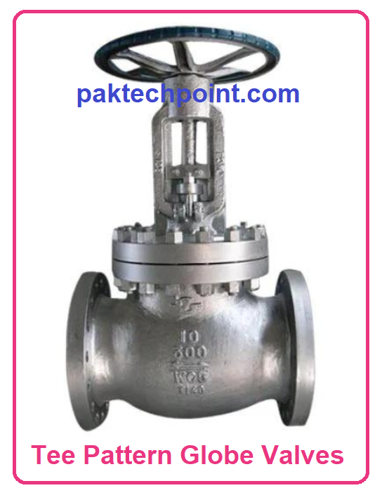
1. Tee Pattern Globe Valves:
Tee pattern globe valves, also known as Z-body globe valves, feature a design that resembles the letter “T.” These valves have a straight flow path through the valve body, making them suitable for applications that require minimal pressure drop. Tee pattern globe valves are commonly used in situations where space constraints are not a concern and where a straight-through flow path is advantageous.
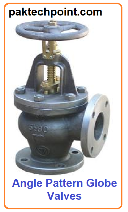
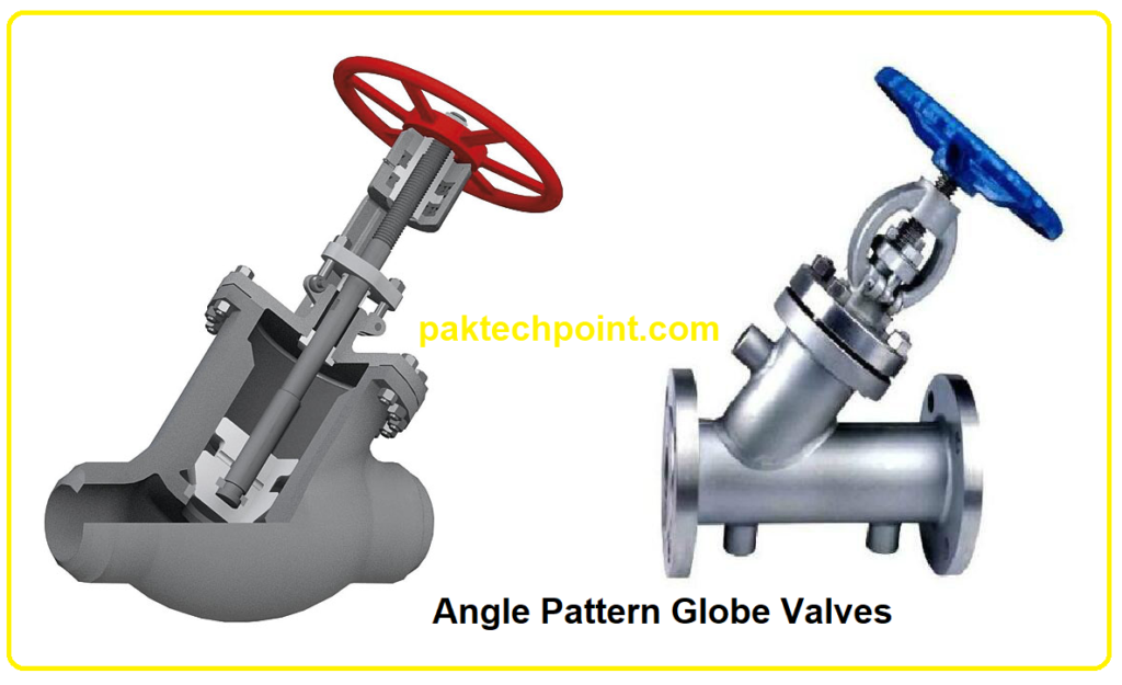
2. Angle Pattern Globe Valves:
Angle pattern globe valves have a design that resembles the letter “Y,” with the inlet and outlet ports oriented at a 90-degree angle to each other. This design allows for the redirection of the fluid flow, making angle pattern globe valves ideal for applications where space is limited. By diverting the flow, these valves can mitigate the impact of turbulence and pressure drop, making them suitable for installations where efficiency and compactness are essential.
3. Wye Pattern Globe Valves:
Wye pattern globe valves, also referred to as Y-body globe valves, are characterized by their Y-shaped design. These valves have an inclined flow path, with the inlet and outlet ports forming an angle. Wye pattern globe valves are often chosen for applications that involve slurries, viscous fluids, or media that may contain solids. The angled flow path helps prevent the accumulation of debris, which can reduce the risk of clogging and enhance overall valve performance.
Each type of globe valve offers distinct advantages based on the specific requirements of the application. Tee pattern globe valves excel in situations where pressure drop needs to be minimized, while angle pattern globe valves are preferred when space constraints are a consideration. Wye pattern globe valves, with their ability to handle challenging fluids, are an excellent choice for applications where debris or solids might be present.
Applications of Globe Valves:
A common use of a globe valve is in a basic water faucet. Imagine turning the knob on a faucet – when you turn it, a disk inside the valve either moves up or down. If you turn the knob all the way, the water stops completely. But if you turn it just a bit, the water flows faster. In bigger industries, globe valves can be used with machines that automatically control them, instead of using your hand.
Inside a globe valve, there’s something called a baffle. This baffle makes the liquid change direction as it goes through the valve. This slows down the flow and reduces the pressure. However, these valves aren’t good for thick liquids or materials that can get stuck in the baffle and block the flow.
Globe valves find applications in diverse industries due to their versatility and precise flow control capabilities. They are commonly used in HVAC systems, process industries, oil and gas refineries, water treatment plants, power generation facilities, and marine systems. Their ability to handle a wide range of flow rates and pressures makes them ideal for both on-off control and throttling.
Advantages and Disadvantages of Globe Valves:
Globe valves offer several advantages, including accurate flow modulation, reliable shut-off capabilities, and suitability for a wide range of flow conditions. However, they also have limitations, such as higher pressure drop compared to some other valve types and potential for flow restriction in fully open positions.
Here’s a table summarizing the advantages and disadvantages of globe valves:
| Advantages of Globe Valves | Disadvantages of Globe Valves |
|---|---|
| Precise Flow Control | Higher Pressure Drop |
| Versatile Applications | Slower Opening and Closing |
| Bidirectional Flow Control | More Complex Design |
| Good Sealing Capabilities | Potential for Cavitation |
| Suitable for Throttling | Limited for Large Pipe Sizes |
| Low Risk of Erosion | Higher Maintenance |
Selecting the Right Globe Valve:
Choosing the right globe valve involves considering factors such as valve sizing, material compatibility, flow characteristics, pressure and temperature ratings, end connections, and actuation methods. Proper selection ensures optimal valve performance and system efficiency.
Maintenance and Operation:
Proper maintenance of globe valves is crucial for their longevity and reliability. Regular preventive maintenance, including inspection, lubrication, and addressing leakage issues, is essential. Troubleshooting common valve problems can help diagnose and resolve issues promptly.
Innovations in Globe Valve Design:
Modern globe valve designs incorporate innovative materials, smart technology, and enhanced sealing mechanisms. Advances in valve materials and digital technology are improving valve performance, reliability, and ease of operation.
Optional Features:
Valves are critical components in fluid control systems, and optional features can enhance their performance and capabilities. Here are some noteworthy optional features that can be incorporated into valve designs to address specific requirements and challenges:
1. Soft Seating for Class VI Shut Off:
Achieving a tight shut-off is crucial to prevent any leakage through the valve when it’s in the closed position. Soft seating involves using materials like elastomers or polymers to create a resilient seal between the disc or plug and the seat. This helps achieve a class VI shut-off, minimizing the potential for any fluid leakage even under demanding conditions.
2. Downstream Silencer for Noise Reduction:
In applications where noise reduction is a concern, a downstream silencer can be added to the valve’s design. This feature helps attenuate the noise generated by the fluid flow as it exits the valve, contributing to a quieter working environment and compliance with noise regulations.
3. Seat Diffuser for Body Protection:
In cases where the fluid being controlled might have erosive or abrasive properties, a seat diffuser can be introduced. This feature acts as a shield, protecting the valve body and internals from the harmful effects of the fluid flow. By mitigating potential damage, the seat diffuser prolongs the valve’s lifespan and maintains its performance.
4. Balanced Pilot for High Tight Shut Off:
For applications requiring an exceptionally high level of shut-off tightness, a balanced pilot design can be utilized. This design utilizes additional components to ensure that the forces acting on the valve are balanced, enhancing the valve’s ability to achieve a tight shut-off even under challenging conditions.
5. Live Loaded Packing for Emission Protection:
In applications demanding low fugitive emissions and extended performance, live loaded packing can be employed. This feature ensures constant pressure on the valve’s packing, maintaining a tight seal and reducing the likelihood of emissions escaping. Live loaded packing enhances the valve’s environmental and operational performance.
Varieties of Bonnet Forms:
The bonnet of a valve plays a crucial role in ensuring its reliable operation under different conditions. Depending on the specific requirements and operating conditions, different bonnet forms can be chosen to enhance valve performance and longevity. Here are some notable bonnet forms and their applications:
1. Standard Bonnet:
The standard bonnet is designed to handle a typical range of temperatures and operating conditions. It provides effective sealing and protection for the valve components within the bonnet. This type of bonnet is suitable for applications where the temperature range falls within standard limits.
2. Normalizing Bonnet:
In cases where the operating temperatures extend beyond the standard range, a normalizing bonnet can be employed. This type of bonnet provides enhanced protection to the gland packing and other components within the bonnet, ensuring their integrity and preventing any adverse effects due to elevated temperatures.
3. Bellows Seal Bonnet:
When high leak protection is a critical requirement, a bellows seal bonnet comes into play. This specialized bonnet design incorporates a bellows assembly that provides an additional layer of sealing against leaks. Bellows seal bonnets are particularly effective in applications where leak prevention is of utmost importance, such as in hazardous or toxic fluid handling.
4. Cryogenic Bonnet:
Operating in extremely low temperatures presents its own set of challenges, including the risk of packing freezing. Cryogenic bonnets are engineered to address this issue. By incorporating specialized materials and insulation, cryogenic bonnets ensure that the valve’s packing remains functional even in frigid conditions, safeguarding the valve’s performance in cryogenic applications.
Globe Valve Trim Options
The trim of a globe valve, which includes components like plugs, discs, and seats, is a critical factor that directly influences the valve’s control capabilities and overall efficiency. Various trim options are available to tailor valve performance to specific applications. Here are some notable trim options and their applications:
1. Multi-Flow (MF) Trim:
The Multi-Flow trim utilizes a single-stage ported cage style design to optimize flow control. This trim is suitable for applications where precise control over fluid flow is required, and the single-stage design ensures efficient performance.
2. Single Stage Multi-Flow (SS) Trim:
The Single Stage Multi-Flow trim features a single-stage drilled hole cage, which provides effective control over flow. This trim option is well-suited for applications where maintaining consistent flow and pressure control is essential.
3. Cascade (CS) Trim:
The Cascade trim is designed for severe service duties, featuring a concentric cage design. This trim option is ideal for applications with challenging conditions and aggressive media, where reliable control and durability are paramount.
4. Variable Stage Cascade (VS) Trim:
The Variable Stage Cascade trim combines both single-stage and multi-stage cage designs to provide enhanced control capabilities. This trim option is versatile and can adapt to a range of flow control requirements, making it suitable for various applications.
5. Spline Trim:
The Spline trim is designed for single-stage micro-flow control, making it well-suited for applications that demand precision control over low flow rates. This trim option ensures accurate control even in scenarios where minimal flow adjustments are necessary.
6. Flash Cone Trim:
The Flash Cone trim employs a multi-stage single path design, optimized for extra low flow conditions. This trim option excels in applications where controlling very low flow rates is critical for maintaining operational efficiency.
7. X-Stream™ Trim:
The X-Stream™ trim offers multi-stage multi-path configuration, specifically engineered for high severity service conditions. This trim option is ideal for applications where extreme conditions, such as high pressures and temperatures, demand exceptional control and reliability.
Trim Characteristics in Globe Valves
Globe valves are indispensable components in fluid control systems, providing efficient and precise regulation of flow. One of the critical factors influencing the performance of globe valves is their trim characteristics. These characteristics dictate how the valve responds to changes in the valve stem position, directly affecting the flow rate. Let’s delve into the four primary trim characteristics found in globe valves: linear, equal percentage, quick opening, and intermediate.
1. Linear Trim:
Linear trim characteristic in globe valves maintains a direct, linear relationship between the valve stem position and the flow rate. This means that a consistent change in the valve stem position results in an equal change in the flow rate. Linear trim is preferred in applications requiring proportional control, where precise adjustments are essential for maintaining system stability and accurate flow rates.
2. Equal Percentage Trim:
Equal percentage trim characteristic introduces a fascinating property where each equal increment of the valve stem position produces an equal percentage change in the flow rate. This feature makes equal percentage trim ideal for applications demanding a broad range of flow control. It excels in scenarios where maintaining accurate control over a wide spectrum of flow rates is critical.
3. Quick Opening Trim:
Quick opening trim is characterized by an immediate and significant increase in the flow rate as the valve stem position is initially adjusted. This characteristic is particularly useful in situations requiring rapid full flow activation. Quick opening trim is often employed in emergency shutdown scenarios or applications where swift system response is paramount.
4. Intermediate Trim:
Intermediate trim characteristic finds a balance between linear and equal percentage characteristics. It offers controlled flow rate changes in response to valve stem adjustments. Intermediate trim is an excellent choice when applications necessitate a combination of proportional control and broader flow rate modulation.
Design Standards of Globe Valves:
Globe valves play a crucial role in various industries, providing precise control over fluid flow. To ensure their functionality, safety, and reliability, these valves are manufactured following specific design standards. These standards guide the design, manufacturing, testing, and certification of globe valves, ensuring that they meet the highest quality and performance requirements. Here are some prominent design standards that govern the production of globe valves:
1. ASME B16.34:
The ASME B16.34 standard outlines the requirements for globe valves, covering aspects such as materials, dimensions, pressure-temperature ratings, and testing procedures. This standard ensures the integrity and performance of globe valves used in different applications.
2. EN 12516-1 / 2:
EN 12516-1 and EN 12516-2 are European standards that specify the design and pressure-temperature ratings for industrial valves, including globe valves. These standards help manufacturers produce valves suitable for various operating conditions and fluid types.
3. API 6A:
API 6A is a standard specifically focused on wellhead equipment and valves used in the oil and gas industry. It ensures that globe valves meet the rigorous demands of wellhead operations, including extreme pressure and temperature conditions.
4. ANSI FCI 70-2:
This standard, published by the Fluid Controls Institute (FCI), provides guidelines for the classification and testing of control valve seat leakage. It ensures that globe valves used in control applications exhibit reliable shut-off capabilities to prevent unintended flow.
5. ASME B16.25 and ASME B16.5:
These ASME standards address the dimensions and tolerances of butt-welding ends and flanged connections, respectively. They ensure proper fitment and sealing of globe valves within piping systems.
6. NACE MR-01-75:
NACE MR-01-75 focuses on material requirements for sulfide stress cracking-resistant metallic materials used in oilfield equipment, including globe valves. This standard helps prevent corrosion-related failures in harsh environments.
7. ISO Standards (ISO 9001, ISO 14001, ISO 15848-1):
ISO standards cover various aspects of quality management, environmental management, and fugitive emissions testing. ISO 15848-1 specifically deals with valve testing for fugitive emissions to reduce environmental impact.
8. Other Standards:
Additional standards like BS1560, BS4504, ASME BPVC Section III, NQA-1, 10CFR50 App. B, 10CFR50 Part 21, RCC-E, RCC-M, CSA Z299, PED, and ATEX may apply based on specific industries, applications, and regions.
Conclusion:
Globe valves continue to be an integral component in fluid control systems across various industries. Their well-established design principles, along with ongoing advancements, make them a dependable choice for applications requiring precise flow modulation and regulation. Understanding the technical aspects of globe valves empowers engineers and industry professionals to select, install, and maintain these valves effectively, contributing to efficient and reliable system operation.
Read Also: Control Valve Types – Explained One by One