This article is about Hazardous Location GRS Conduits & Liquid Tight (LT) Flexible Conduit System (Class 1, Zone or Div 2) Installation, Material Selection Guide & Technical Specification for commercial buildings, plants and refinery projects as per international codes and standards.
Hazardous Location GRS Conduits & LT Flex Conduit System (Class 1, Zone or Div 2), Installation
Installation and Identification of GRS and LT Flex Conduit Systems (Before Concealment and Cable Pulling)
| Complete Runs: Raceways shall be installed complete between outlet, junction, or splicing points prior to the installation of conductors. [NFPA 70, NEC 300.18 (A)] |
| GRS Conduit Fill Percentage: Conduit fill shall not exceed the maximum fill specified in attachment 1, NEC Chapter 9, Table 1 & 4 and Notes to Tables. Commentary Note: Because conductor sizes and insulation thickness of IEC and SASO type wires and cables vary from those of NEC type wires and cables, actual dimensions (outside diameters) must be used to calculate conduit fill and maximum number of wires allowed in conduit, instead of NEC tables. |
| Conductor Fill Percentages for Conduit Nipple: Conductor fill percentage for a conduit nipple shall be permitted to be at 60% if the nipple is not longer than 24 inches (610mm). [NFPA 70, NEC Chapter 9, Notes to Tables, Note 4] |
| Field Bends for GRS Conduit – How Made: Bends of GRS conduit shall be made so that the conduit is not damaged and the internal diameter of the conduit is not effectively reduced. The radius of the curve of any field bend to the centerline of the conduit shall not be less than indicated in Table 2, Chapter 9 (Attachment 2). [NFPA 70, NEC 344.24] |
| Bends – Number in One Run: There shall not be more than the equivalent of four quarter bends (360 degrees total) between pull points, for example, conduit bodies and boxes. [NFPA 70, NEC 344.26] |
| Cutting: Verify that conduit threads are properly cut. Conduit shall be cut using a saw or a roll cutter (pipe cutter). Care should be taken to ensure a straight cut. [NFPA 70, NEC 110.12] |
Reaming and Threading:
All cut ends shall be reamed or otherwise finished to remove rough edges. Where conduit is threaded in the field, a standard cutting die with a 1 in 16 taper (3⁄4-in. taper per foot) shall be used. [NFPA 70, NEC 344.28]
GRS Conduit Fastening:
GRS conduit shall be securely fastened within 900 mm (3 ft) of each outlet box, junction box, device box, cabinet, conduit body, or other conduit termination. Fastening shall be permitted to be increased to a distance of 1.5 m (5 ft) where structural members do not readily permit fastening within 900 mm (3 ft). Where approved, conduit shall not be required to be securely fastened within 900 mm (3 ft) of the service head for above-the-roof termination of a mast. [NFPA 70, NEC 344.30 (A)]
GRS Conduit Supports:
GRS conduit shall be supported in accordance with one of the following.
(1) Conduit shall be supported at intervals not exceeding 3 m (10 ft).
(2) The distance between supports for straight runs of conduit shall be permitted in accordance with Table 344.30(B)(2) (See Attachment 3), provided the conduit is made up with threaded couplings and such supports prevent transmission of stresses to termination where conduit is deflected between supports.
(3) Exposed vertical risers from industrial machinery or fixed equipment shall be permitted to be supported at intervals not exceeding 6 m (20 ft) if the conduit is made up with threaded couplings, the conduit is supported and securely fastened at the top and bottom of the riser, and no other means of intermediate support is readily available.
(4) Horizontal runs of RMC supported by openings through framing members at intervals not exceeding 3 m (10 ft) and securely fastened within 900 mm (3 ft) of termination points shall be permitted. [NFPA 70, NEC 344.30 (B)]
Raceways Used as Means of Support:
Raceways shall be used only as a means of support for other raceways, cables, or nonelectrical equipment under any of the following conditions:
(1) Where the raceway or means of support is identified for the purpose
(2) Where the raceway contains power supply conductors for electrically controlled equipment and is used to support Class 2 circuit conductors or cables that are solely for the purpose of connection to the equipment control circuits
(3) Where the raceway is used to support boxes or conduit bodies in accordance with 314.23 or to support luminaires in accordance with 410.36(E). [NFPA 70, NEC 300.11 (B)]
| Number and Size of Conductors in Raceway: The number and size of conductors in any raceway shall not be more than will permit dissipation of the heat and ready installation or withdrawal of the conductors without damage to the conductors or to their insulation. [NFPA 70, NEC 300.17] |
| Use of LT flex in Ducts and Plenum Chambers: LT Flex conduit shall be permitted, in lengths not to exceed 1.2 m (4 ft), to connect physically adjustable equipment and devices permitted to be in ducts and plenum chambers. The connectors used with LT Flex conduit shall effectively close any openings in the connection. [NFPA 70, NEC 300.22 (B)] |
| Conduit Fittings: Conduit fittings for outdoor rigid steel conduit and liquid-tight flexible metal conduit shall be cast or forged steel, cast iron or malleable iron, either hot-dip galvanized (preferably), or zinc electroplated as supplied by the manufacturer. No aluminum fittings or fitting accessories such as covers, sealing fitting plugs, etc., shall be used outdoor. Only malleable iron sealing fittings shall be used. Gray cast iron split type (EYSR) retrofit sealing fittings may be used if required for repair purposes. |
| Couplings and Connectors: (A) Threadless – Threadless couplings and connectors used with conduit shall be made tight. Where buried in masonry or concrete, they shall be the concretetight type. Where installed in wet locations, they shall comply with 314.15. Threadless couplings and connectors shall not be used on threaded conduit ends unless listed for the purpose. (B) Running – Threads. Running threads shall not be used on conduit for connection at couplings. [NFPA 70, NEC 344.42] |
| Conduit Support – Welding: Metal raceways shall not be supported, terminated, or connected by welding to the raceway unless specifically designed to be or otherwise specifically permitted to be in this Code. [NFPA 70, NEC 300.18 (B)] |
| Threads of plugs, junction boxes and other fittings shall be lightly lubricated with a rust preventive grease such as Crouse Hinds thread lubricant (1000405418) or High Purity Goop (1000174895) before assembly. |
| Threading: Conduit and threaded conduit fittings shall have tapered (NPT) threads in accordance with ANSI/ASME B1.20.1. |
| Connections: Verify that conduit connections are wrench tight. [NFPA 70, NEC 110.3 (B)] |
Raceways Exposed to Different Temperatures – Expansion Fittings:
Raceways shall be provided with expansion fittings where necessary to compensate for thermal expansion and contraction.
FPN: Table 352.44 (Attachment 3) and Table 355.44 (Attachment 4) provide the expansion information for polyvinyl chloride (PVC) and for reinforced thermosetting resin conduit (RTRC), respectively. A nominal number for steel conduit can be determined by multiplying the expansion length in Table 352.44 by 0.20. The coefficient of expansion for steel electrical metallic tubing, intermediate metal conduit, and rigid conduit is 1.170 × 10⁻⁵ (0.0000117 mm per mm of conduit for each °C in temperature change) [0.650 × 10⁻⁵ (0.0000065 in. per inch of conduit for each °F in temperature change)]. [NFPA 70, NEC 300.7 (B)]
| Locknuts: Verify that locknuts are installed correctly. [NFPA 70, NEC 110.3 (B)] |
| Bushings: Where a conduit enters a box, fitting, or other enclosure, a bushing shall be provided to protect the wire from abrasion unless the design of the box, fitting, or enclosure is such as to afford equivalent protection. FPN: See 300.4(G) for the protection of conductors sizes 4 AWG and larger at bushings. [NFPA 70, NEC 344.46] |
| Protection Against Physical Damage – Insulated Fittings: Where raceways contain 4 AWG or larger insulated circuit conductors and these conductors enter a cabinet, box, enclosure, or raceway, the conductors shall be protected by a substantial fitting providing a smoothly rounded insulating surface, unless the conductors are separated from the fitting or raceway by substantial insulating material that is securely fastened in place. [NFPA 70, NEC 300.4 (G)] |
| Process piping shall not be used to support conduits, except with the Proponent’s approval. If process piping is used to support conduits, adequate corrosion protection at the interface between the piping and support fittings shall be provided. Commentary Note 8.10: Plant structural members used as supports for conduit and other electrical equipment are outside the scope of this Section. Attachment hardware (clamps, bolts, nuts, etc.) must however, comply with the requirements of this Section. |
| Dissimilar Metals: Where practicable, dissimilar metals in contact anywhere in the system shall be avoided to eliminate the possibility of galvanic action. Aluminum fittings and enclosures shall be permitted to be used with steel RMC, and steel fittings and enclosures shall be permitted to be used with aluminum RMC where not subject to severe corrosive influences. [NFPA 70, NEC 344.14] |
| Uses Permitted: LFMC shall be permitted to be used in exposed or concealed locations as follows: (1) Where conditions of installation, operation, or maintenance require flexibility or protection from liquids, vapors, or solids (2) As permitted by 501.10(B), 502.10, 503.10, and 504.20 and in other hazardous (classified) locations where specifically approved, and by 553.7(B) (3) For direct burial where listed and marked for the purpose [NFPA 70, NEC 350.10] |
| Uses Not Permitted: LFMC shall not be used as follows: (1) Where subject to physical damage (2) Where any combination of ambient and conductor temperature produces an operating temperature in excess of that for which the material is approved. [NFPA 70, NEC 350.12] |
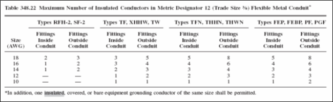
| Number of Conductors or Cables in LT Flex Conduit: (A) Metric Designators 16 through 103 (Trade Sizes 1⁄2 through 4). The number of conductors shall not exceed that permitted by the percentage fill specified in Table 1, Chapter 9 (Attachment 1). Cables shall be permitted to be installed where such use is not prohibited by the respective cable articles. The number of cables shall not exceed the allowable percentage fill specified in Table 1, Chapter 9 (Attachment 1). (B) Metric Designator 12 (Trade Size 3⁄8). The number of conductors shall not exceed that permitted in Table 348.22 (Attachment 6), “Fittings Outside Conduit” columns. [NFPA 70, NEC 350.22] |
| Bends – How Made: Bends in conduit shall be so made that the conduit will not be damaged and the internal diameter of the conduit will not be effectively reduced. Bends shall be permitted to be made manually without auxiliary equipment. The radius of the curve to the centerline of any bend shall not be less than required in Table 2, Chapter 9 (Attachment 2) using the column “Other Bends.” [NFPA 70, NEC 350.24] |
LT Flex Conduit Fastening:
LFMC shall be securely fastened in place by an approved means within 300 mm (12 in.) of each box, cabinet, conduit body, or other conduit termination and shall be supported and secured at intervals not to exceed 1.4 m (41⁄2 ft).
Exception No. 1: Where LFMC is fished between access points through concealed spaces in finished buildings or structures and supporting is impractical.
Exception No. 2: Where flexibility is necessary after installation, lengths shall not exceed the following:
(1) 900 mm (3 ft) for metric designators 16 through 35 (trade sizes 1⁄2 through 11⁄4)
(2) 1200 mm (4 ft) for metric designators 41 through 53 (trade sizes 11⁄2 through 2)
(3) 1500 mm (5 ft) for metric designators 63 (trade size 21⁄2) and larger
Exception No. 3: Lengths not exceeding 1.8 m (6 ft) from a luminaire terminal connection for tap conductors to luminaires, as permitted in 410.117(C).
Exception No. 4: Lengths not exceeding 1.8 m (6 ft) from the last point where the raceway is securely fastened for connections within an accessible ceiling to luminaire(s) or other equipment. [NFPA 70, NEC 350.30 (A)]
| LT Flex Conduit Supports: Horizontal runs of LFMC supported by openings through framing members at intervals not greater than 1.4 m (41⁄2 ft) and securely fastened within 300 mm (12 in.) of termination points shall be permitted. [NFPA 70, NEC 350.30 (B)] |
| LT Flex Conduit Connectors: Angle connectors shall not be used for concealed raceway installations. [NFPA 70, NEC 350.42] |
| Raceway Identification – Feeder & Branch Circuit Conduits: No labeling is required for raceways with readily identifiable terminations within the same room. [ANSI A13.1] |
| Raceway Identification – Feeder & Branch Circuit Conduits: In accessible ceiling spaces and exposed in unfinished areas, label conduit with panel and circuit numbers of conductors routed through the conduit. Label conduit at all wall penetrations and connections to all panels, junction boxes and equipment served. [ANSI A13.1] |
| Raceway Identification – Feeder & Branch Circuit Conduits: Use a black indelible marker and hand print label in a clear workmanlike manner, or use stencil or black paint to provide a clearly legible label. [ANSI A13.1] |
| Raceway Identification – Empty Conduits: Provide labels with description of purpose, and location of opposite end, on each of the conduits provided for future. [ANSI A13.1] |
Commissioning of GRS and LT Flex Conduit Systems (After Cable Pulling and Before Cover and Gasket Installation)
| Re-Checking of Conduit Fill Percentage: Conduit fill shall not exceed the maximum fill specified in attachment 1, NEC Chapter 9, Table 1 & 4 and Notes to Tables. |
| Splices in Conduit Bodies: Only those conduit bodies that are durably and legibly marked by the manufacturer with their volume shall be permitted to contain splices. [NFPA 70, NEC 314.16 (C)(2)] |
| Length of Free Conductors at Outlets, Junctions, and Switch Points: At least 150 mm (6 in.) of free conductor, measured from the point in the box where it emerges from its raceway or cable sheath, shall be left at each outlet, junction, and switch point for splices or the connection of luminaires or devices. Where the opening to an outlet, junction, or switch point is less than 200 mm (8 in.) in any dimension, each conductor shall be long enough to extend at least 75 mm (3 in.) outside the opening. Exception: Conductors that are not spliced or terminated at the outlet, junction, or switch point shall not be required to comply with 300.14. [NFPA 70, NEC 300.14] |
| Mechanical Continuity – Raceways and Cables: Metal or nonmetallic raceways, cable armors, and cable sheaths shall be continuous between cabinets, boxes, fittings, or other enclosures or outlets. Exception No. 1: Short sections of raceways used to provide support or protection of cable assemblies from physical damage shall not be required to be mechanically continuous. Exception No. 2: Raceways and cables installed into the bottom of open bottom equipment, such as switchboards, motor control centers, and floor or pad-mounted transformers, shall not be required to be mechanically secured to the equipment. [NFPA 70, NEC 300.12] |
| Mechanical and Electrical Continuity – Conductors: Conductors in raceways shall be continuous between outlets, boxes, devices, and so forth. There shall be no splice or tap within a raceway unless permitted by 300.15; 368.56(A); 376.56; 378.56; 384.56; 386.56; 388.56; or 390.6. [NFPA 70, NEC 300.13 (A)] |
| Raceways Exposed to Different Temperatures – Sealing: Where portions of a cable raceway or sleeve are known to be subjected to different temperatures and where condensation is known to be a problem, as in cold storage areas of buildings or where passing from the interior to the exterior of a building, the raceway or sleeve shall be filled with an approved material to prevent the circulation of warm air to a colder section of the raceway or sleeve. An explosionproof seal shall not be required for this purpose. [NFPA 70, NEC 300.7 (A)] |
| Installation of Conductors with Other Systems: Raceways or cable trays containing electrical conductors shall not contain any pipe, tube, or equal for steam, water, air, gas, drainage, or any service other than electrical. [NFPA 70, NEC 300.8] |
GRS and LT Flex Conduit Systems (After Sealing and Covering, and Before Energization)
| Electrical Continuity of Metal Raceways: Metal raceways for conductors shall be metallically joined together into a continuous electric conductor and shall be connected to all boxes, fittings, and cabinets so as to provide effective electrical continuity. Unless specifically permitted elsewhere in this Code, raceways shall be mechanically secured to boxes, fittings, cabinets, and other enclosures. Exception: Short sections of raceways used to provide support or protection of cable assemblies from physical damage shall not be required to be made electrically continuous. [NFPA 70, NEC 300.10] |
| LT Flex Conduit Grounding and Bonding: Where used to connect equipment where flexibility is required after installation, an equipment grounding conductor shall be installed. Where flexibility is not required after installation, LFMC shall be permitted to be used as an equipment grounding conductor when installed in accordance with 250.118(6). Where required or installed, equipment grounding conductors shall be installed in accordance with 250.134(B). Where required or installed, equipment bonding jumpers shall be installed in accordance with 250.102. FPN: See 501.30(B), 502.30(B), 503.30(B), 505.25(B), and 506.25(B) for types of equipment grounding conductors. [NFPA 70, NEC 350.60] |
Induced Currents in Ferrous Metal Enclosures or Ferrous Metal Raceways:
(A) Conductors Grouped Together. Where conductors carrying alternating current are installed in ferrous metal enclosures or ferrous metal raceways, they shall be arranged so as to avoid heating the surrounding ferrous metal by induction. To accomplish this, all phase conductors and, where used, the grounded conductor and all equipment grounding conductors shall be grouped together.
(B) Individual Conductors. Where a single conductor carrying alternating current passes through metal with magnetic properties, the inductive effect shall be minimized by
(1) cutting slots in the metal between the individual holes through which the individual conductors pass or
(2) passing all the conductors in the circuit through an insulating wall sufficiently large for all of the conductors of the circuit. [NFPA 70, NEC 300.20]
| Expansion fittings of metal raceways shall be made electrically continuous by equipment bonding jumpers or other means. [NFPA 70, NEC 250.98] |
| Field cut conduit threads shall be coated with a zinc rich protective coating. |
| Conduit Fittings – After installation, any bare metal must be PVC touched up, without sandblasting. |
| Spread of Fire or Products of Combustion: Electrical installations in hollow spaces, vertical shafts, and ventilation or air-handling ducts shall be made so that the possible spread of fire or products of combustion will not be substantially increased. Openings around electrical penetrations through fire-resistant-rated walls, partitions, floors, or ceilings shall be firestopped using approved methods to maintain the fire resistance rating. [NFPA 70, NEC 300.21] |
| Fireproofing: Verify that conduits are fireproofed where needed, per SAES-B-006. |
International Codes & Standards
| 1. NFPA 70 – National Electrical Code (NEC), 2008 |
| 2. SAES-P-104 – Wiring Methods and Materials, January 2008 |
| 3. SAES-P-100 – Basic Power System Design Criteria, June 2007 |
| 4. 15-SAIP-50 – Inspection Procedure for Conduit and Cable Seals, August 2004 |
| 5. ANSI/ASME B1.20.1 – Pipe Threads, General Purpose (INCH), 2006 |
| 6. NECA 101 – Installing Steel Conduits (Rigid , IMC, EMT), 2006 |
| 7. ANSI A13.1 – Operational and Warning Signs |
Table 1, Percent of Cross Section of Conduit and Tubing for Conductors – NFPA 70

Table 2, Radius of Conduit and Tubing Bends – NFPA 70
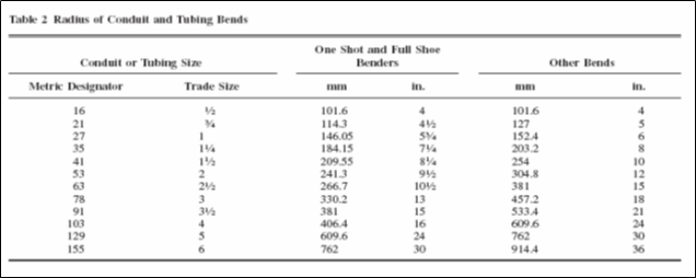
Table 344.30(B)(2), Supports for Rigid Metal Conduit – NFPA 70
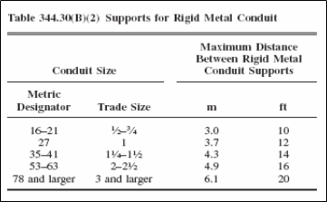
Table 352.44, Expansion Characteristics of PVC Rigid NonMetallic Conduit Coefficient of Thermal Expansion – NFPA 70
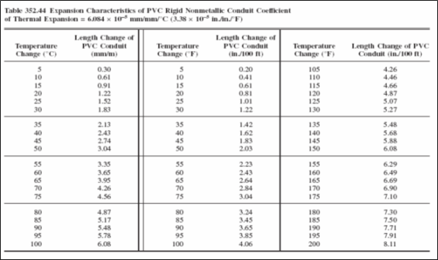
Table 355.44, Expansion Characteristics of Reinforced Thermosetting Resin Conduit (RTRC) – NFPA 70
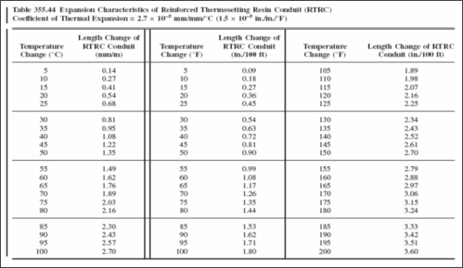
Table 348.22, Maximum Number of Insulated Conductors in Metric Designator 12 (Trade Size 3⁄8) Flexible Metal Conduit* – NFPA 70