The design philosophy for most reciprocating machines is to minimize the unbalanced inertial and pressure forces and to absorb the remainder of the energy with the large mass of the foundation. The most common way to do this in process compressors is using the balanced opposed horizontal cylinder design. Reciprocating compressors inherently vibrate more than centrifugal machines. Due to the higher levels of “normal” vibration, it is essential to get the transducers as close to the sources of vibration as possible. The design of reciprocating compressors allows them to withstand higher vibration and more extreme operating conditions than centrifugal machines.
Rotation-related vibration (which includes synchronous vibration components) is the vibration resulting from the cyclic forces related to crankshaft rotating speed. Most inertial and pressure forces cause vibrations related to one or two times the crankshaft rotating speed.
Free vibration is a result of impulse forces (impact-type events) which result in vibration close to the natural frequency of the machine. The natural frequency of these machines tends to be much higher than running speed. Impact events include broken or chipped parts, the introduction of foreign particles into the cylinder, excessive clearance in the wrist pin bushing, loose piston nuts or other loose components in the running gear assembly. Due to the low running speed and high system natural frequency, free vibration signals are generally of a much higher frequency than rotation-related vibration signals for reciprocating compressors.
A. Rotation-Related Vibration Detection
Shaft Relative Vibration Monitoring on compressor main bearings and motor/driver inboard and outboard bearings using 3300/16 Dual Vibration Monitors and a 3300 Proximity Transducer System
Benefits
Typical mechanical problems that proximity probes can detect when installed on the crankshaft main bearings and the bearings on the driver include:
- Increases in bearing clearance due to bearing wear.
- Unbalance.
- Misalignment between crankshaft bearings or between the crankshaft and the driver.
- System Description
The proximity transducer vibration monitoring system consists basically of two components: the 3300 Proximity Transducer System (including a Keyphasor® transducer) and a 3300/16 Dual Vibration Monitor.Proximity Probe Installation
The installation and use of proximity probes to detect machinery faults on fluid film bearing rotating machines is well documented, and does not vary for reciprocating compressors. Refer to Bently Nevada Applications Note AN028 for information on how to properly install these transducers.- Frame Vibration Monitoring using 3300/55 Dual Velocity Monitors and Velomitor® Transducers
The cylinders in balanced-opposed compressors are physically offset, causing moments to be generated on the crankshaft. Additionally, the pressure forces across the machine can become unbalanced due to process changes, valve unloaders or damaged valve assemblies. These forces are transmitted through the bearing to the frame, resulting in crankcase vibration at one or two times machine running speed. Frequencies on the order of ½x and 2x the machine speed and their harmonics can also occur on reciprocating compressors due to their layout. Excessive amplitudes at these frequencies may indicate mechanical or operational problems. Velomitor® Piezo-velocity Sensors are ideal for detecting machinery problems on reciprocating compressors where rotation-related vibration is transmitted to the compressor frame. Velomitor® Sensors eliminate the cross-axis sensitivity problems inherent to moving coil velocity sensors. At the same time, they have a better signal-to-noise ratio at the low running speed frequency of reciprocating machines when compared to standard accelerometers.
Bently Nevada highly recommends that customers use frame vibration as a shutdown parameter. It is a recommended shutdown parameter in API 618.
Benefits
Typical operational problems that the Velomitor® Sensor and monitor can detect include:
-
-
-
- Imbalance due to an unusual pressure differential or inertial imbalance.
- Looseness in the foundation attachment (such as deteriorating grout or shims).
- High moments caused by excessive rod load.
-
-
System Description
The proximity transducer vibration monitoring system consists basically of two components: the 3300 Proximity Transducer System (including a Keyphasor® transducer) and a 3300/16 Dual Vibration Monitor.
Proximity Probe Installation
The installation and use of proximity probes to detect machinery faults on fluid film bearing rotating machines is well documented, and does not vary for reciprocating compressors. Refer to Bently Nevada Applications Note AN028 for information on how to properly install these transducers.
Frame Vibration Monitoring using 3300/55 Dual Velocity Monitors and Velomitor® Transducers
The cylinders in balanced-opposed compressors are physically offset, causing moments to be generated on the crankshaft. Additionally, the pressure forces across the machine can become unbalanced due to process changes, valve unloaders or damaged valve assemblies. These forces are transmitted through the bearing to the frame, resulting in crankcase vibration at one or two times machine running speed. Frequencies on the order of ½x and 2x the machine speed and their harmonics can also occur on reciprocating compressors due to their layout. Excessive amplitudes at these frequencies may indicate mechanical or operational problems. Velomitor® Piezo-velocity Sensors are ideal for detecting machinery problems on reciprocating compressors where rotation-related vibration is transmitted to the compressor frame. Velomitor® Sensors eliminate the cross-axis sensitivity problems inherent to moving coil velocity sensors. At the same time, they have a better signal-to-noise ratio at the low running speed frequency of reciprocating machines when compared to standard accelerometers.
Bently Nevada highly recommends that customers use frame vibration as a shutdown parameter. It is a recommended shutdown parameter in API 618.
Benefits
Typical operational problems that the Velomitor® Sensor and monitor can detect include:
- Imbalance due to an unusual pressure differential or inertial imbalance.
- Looseness in the foundation attachment (such as deteriorating grout or shims).
- High moments caused by excessive rod load.
System Description
The frame vibration detection system consists of two components: the Velomitor® Piezo-Velocity or Velomitor® XA Sensor and the 3300/55 Dual Velocity Monitor. The Velomitor® Sensor employs an accelerometer with a piezoelectric crystal at its core along with a low noise amplifier /integrator that provides an output in velocity units. The result is a small sensor with no moving parts, integrated electronics and a virtually unlimited lifespan. The transducer provides a vibration signal in velocity units.
Applications
The Velomitor® transducer is ideally suited for measuring casing vibration on reciprocating compressors with a running speed above 270 rpm. For reciprocating compressors with a normal operating speed between 90 and 270 rpm, use the Velomitor® CT Sensor to ensure a better frequency response at lower frequencies.
Installation of the Velomitor® Piezo-velocity Sensors The best locations to mount Velomitor® Sensors are on the crankshaft frame in the horizontal axis between each pair of cylinders. Mounting Velomitor® transducers at the bearing level is preferred, as it places the transducers in the direct path of the forces acting on the machine.
Limitations of the Velocity Monitoring System
When applying velocity measurements on reciprocating machinery, it is important to understand the effect that the Timed OK/Channel Defeat and latching have on the behavior of the alarms. This is particularly true when a catastrophic failure occurs from an impact-type event. Impact-type events can result in vibration many orders of magnitude greater than the typically rated 50 in/sec for a Velomitor® Sensor. This condition can force the transducer to operate well outside its linear range and will indicate to the monitoring system that the transducer is in a fault condition (Not OK).
In order to prevent a missed trip (false alarm) due to an intermittent wire connection, Bently Nevada monitors are shipped with Timed OK/Channel Defeat enabled. This means that if there is a fault condition, the channel is disabled and the alarms are bypassed for 3 to 6 seconds. If the Timed OK/Channel Defeat is enabled and an impact event occurs, the transducer may be driven outside its linear range. The monitoring system will indicate a transducer failure, bypassing the alarms. Therefore, you will not get the alarm annunciation you are expecting. Furthermore, if the alarm relays are wired to shutdown the machine, the impact event could prevent automatic shutdown of the machine from the velocity monitor.
The above scenario may be an acceptable situation if you have accelerometers installed to complement your velocity measurement or if you have multiple velocity transducers. Even so, a large impact could cause all velocity transducers and accelerometers to go Not OK. If you are using a stand alone velocity monitor and a single input, this is certainly not a favorable situation.
To ensure machinery protection, the possibility of missed trips should be virtually eliminated. To do this, disable the Timed /OK Channel Defeat feature simply by changing the monitor configuration. With this feature disabled, an impact event may still cause the transducer to operate outside its linear range, and the monitor will still indicate a transducer failure. However, the monitor will also go into alarm and the alarm relays will shut down the machine if they are wired for shutdown.
B. Free Vibration Detection using 3300/25 Dual Accelerometer Monitor and Accelerometers
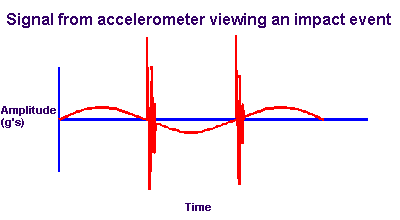
Placing accelerometers over each cylinder provides the best method to detect machinery problems due to impact-type events. Impact-related events characteristically cause free vibrations and are typically due to liquid ingestion into the cylinder or mechanical problems/looseness in the crosshead and piston assembly. Accelerometers send signals into the 3300/25 Dual Accelerometer Monitor to detect high frequency vibrations. They can detect impact-type machinery problems better than a velocity measurement due to the high frequency vibrations caused by impact events. Under normal conditions, the vibration level should be very small. As impacts occur, the vibration level increases and the waveform will look like a classic impact ring-down response over each stroke, as shown in the figure below. The large increase in amplitude should be readily apparent from looking at an acceleration waveform generated by an impact.
It is also recommended that crosshead acceleration also be used as a shutdown parameter to protect the machine.
Benefits
The benefits of monitoring free vibration using accelerometers include the ability to detect the following machinery faults:
- Liquid ingestion into the cylinder.
- Excessive crosshead clearance.
- Loose or cracked nuts or bolts.
- Excessive clearance in the wrist pin bushing.
- Detonation on power cylinders for integral engine compressors.
Installation of the accelerometer
To detect impact-type events, mount an accelerometer on each cylinder over the crosshead, distance piece or cylinder. For best results, mount the accelerometer at or near the distance piece in the vertical plane.