This article describes the minimum requirements for fans for use with HVAC systems, including axial fans, centrifugal fans and ventilators.
HVAC Fans Selection Guide | Axial Fans | Ventilators
Submittals
Product data shall include rated capacities, furnished specialties, and accessories for each type of product indicated and include the following:
- Certified fan performance curves with system operating conditions indicated
- Certified fan sound-power ratings
- Motor ratings and electrical characteristics, plus motor and electrical accessories
- Material gages
- Dampers, including housings, linkages, and operators
Shop Drawings:
- Detail equipment assemblies and indicate dimensions, weights, loads, required clearances, method of field assembly, components, and location and size of each field connection.
- Wiring diagrams indicating power, signal and control wiring. Wiring diagrams shall differentiate between manufacturer installed and field installed wiring.
Operation, installation and maintenance data shall be submitted for fans to including operation, installation and maintenance manuals.
Quality Assurance
- Electrical components, devices, and accessories shall be listed and labeled as defined in NFPA 70, Article 100, by a testing agency acceptable to authorities having jurisdiction, and marked for intended use.
- Products shall comply with performance requirements and shall be licensed to use the AMCA Certified Ratings Seal.
- Motors and electrical accessories shall comply with NEMA standards.
- Fan operating limits shall be classified according to AMCA 99.
- Sound power level ratings shall comply with AMCA 301.
- Fans shall be factory tested according to AMCA 300. Fans shall be labeled with the AMCA Certified Ratings Seal.
- Fan performance ratings shall establish flow rate, pressure, power, air density, speed of rotation, and efficiency by factory tests and ratings in accordance with AMCA 210.
HVAC Axial Fans
This Article describes the minimum requirements for axial fans for indoor installation including tube axial and vane axial fans. Axial fans consist of fan wheel and housing, straightening vane section (as required by application), factory mounted motor with belt or direct drive, inlet cone and accessories.
Housings shall be steel or galvanized steel with inlet bell and diffuser sections.
a. Inlet and outlet connections shall have outer mounting frame and companion flanges. Inlet cone shall be welded to fan raceway.
b. Guide vane section shall consist of integral guide vanes downstream from fan wheel designed to straighten airflow.
c. Mixed flow outlet connections shall be one or two flanged discharge(s) perpendicular to fan inle
Wheels shall be cast aluminum, axial flow type, with airfoil shaped blades mounted on cast iron wheel plate keyed to shaft with solid-steel key.
Fan hub and blade bearing assemblies shall be cast aluminum, machined and fitted with threaded bearing wells to receive blade-bearing assemblies.
a. Blades shall be replaceable, cast aluminum; factory mounted and balanced to hub assembly.
b. Fan shaft shall be turned, ground, and polished steel designed to operate at no more than 70 percent of first critical speed at top of fan’s speed range.
Shaft bearings shall be radial, self-aligning ball or roller bearings. Lubrication lines shall be extended to the outside of the casing and terminated with grease fittings.
a. Ball bearing rating life shall be ABMA 9, L10 of 100,000 hours.
b. Roller bearing rating life shall be ABMA 11, L10 of 100,000 hours.
Direct driven axial fans shall have motors encased in housing, outside of airstream, factory wired to disconnect switch located on outside of fan housing.
Belt driven axial fans shall be factory mounted, with final alignment and belt adjustment made after installation.
a. Service factor based on fan motor shall be 1.
b. Fan pulleys shall be cast iron with split, tapered bushing; dynamically balanced at factory.
c. Motor pulleys shall be adjustable pitch for use with motors through 5 hp; fixed pitch for use with motors larger than 5 Pulleys shall be selected so pitch adjustment is at the middle of adjustment range at fan design conditions.
d. Belts shall be oil resistant, non-sparking, and non-static and shall be matched sets for multiple belt drives.
e. Belt guards shall be fabricated of steel for motors mounted on outside of fan cabine f. Motor mounts shall be adjustable base.
Accessories, when required by fan application:
a. Companion flanges shall be rolled steel flanges.
b. Inlet and outlet screens shall be wire mesh on fans not connected to ductwork.
c. Backdraft dampers shall be butterfly style, for mounting with flexible connection to the discharge of fan or direct mounted to the discharge diffuser section.
d. Stall alarm probes shall be a sensing probe capable of detecting fan operation in stall and signaling control device
e. Flow measurement ports shall be pressure measurement taps installed in the inlet of fan to detect and signal airflow readings to temperature control systems.
Inlet vanes shall be adjustable; with peripheral control linkage operated from outside of airstream, bronze sleeve bearings on each end of vane support, and provision for manual or automatic operation.
Motors
a. Motor Construction shall be NEMA MG 1, general purpose, continuous duty, Design
b. Enclosure type shall be open dripproof or totally enclosed, fan cooled based on job requirements.
Sheet metal parts shall be factory prime coated before final assembly with exterior surfaces having a factory applied baked enamel finish coat after assembly after assembly.
HVAC Centrifugal Fans
 This Article describes the minimum requirements for centrifugal fans for use with HVAC systems. Centrifugal fans packaged as part of central station air handling units or fan coil units are specified in those sections of this standard and are not a part of this section. Smaller units are specified in this section under the heading of ventilators. Centrifugal fans in this section consist of factory fabricated, assembled, tested and finished belt driven centrifugal fans with housing, wheel, fan shaft, bearings, motor, drive assembly and support structure.
Centrifugal fan and vent set housings shall be formed and reinforced steel panels to make curved scroll housings with shaped cutoff, spun-metal inlet bell, and doors or panels to allow access to internal parts and components.
- Panel bracing shall be steel angle or channel iron member supports for mounting and supporting fan scroll, wheel, motor, and accessories.
- Fabrication class shall be AMCA 99, Class I, II or III depending on fan design pressure. c. Horizontal flanged split housing shall be bolted construction.
- Plug fans shall be fabricated without fan scroll and volute housing, with steel cabinet.
- Tubular centrifugal fans shall be fabricated with a tubular housing from formed and reinforced steel panels with welded seams and the following:
(i) Outlet guide vanes
(ii) Motor and disconnect switch
(iii) Spun inlet cone with flange
(iv) Outlet flange
(v) Brackets suitable for horizontal or vertical mounting
Backward inclined fan wheels shall be steel, aluminum or one piece, fiberglass reinforced plastic construction with curved inlet flange, back plate, backward inclined blades welded or riveted to flange and back plate; or cast iron or cast steel hub riveted to back plate and fastened to shaft with set screws.
Forward curved fan wheels shall be black enameled or galvanized steel construction with inlet flange, back plate, shallow blades with inlet and tip curved forward in direction of airflow, mechanically secured to flange and back plate; cast steel hub swaged to back plate and fastened to shaft with set screws.
Airfoil fan wheels shall be steel construction with smooth curved inlet flange; heavy back plate; hollow die formed, airfoil shaped blades continuously welded at tip flange and back plate; cast iron or cast steel hub riveted to back plate and fastened to shaft with set screws.
Shafts
a. Shafts shall be statically and dynamically balanced and selected for continuous operation at maximum rated fan speed and motor horsepower, with final alignment and belt adjustment made after installation.
b. Shafts shall be turned, ground, and polished hot rolled steel with keyway and shipped with a protective coating of lubricating oil.
c. Shafts shall be designed to operate at no more than 70 percent of first critical speed at top of fan’s speed range.
Bearings
a. Pre-lubricated and sealed shaft bearings shall be self aligning, pillow block type ball bearings with an AMCA 9, L10 ball bearing rated life of 120,000 hours.
b. Grease lubricated shaft bearings with self-aligning, pillow block type, tapered roller bearings and double locking collars and two piece, cast iron housing shall have an AMCA 11, L10 roller bearing rated life of 120,000 hours.
c. Grease lubricated shaft bearings with self-aligning, pillow block type, ball or roller bearings with adapter mount and two piece, cast iron housing shall have the following applicable bearing life:
(i) Ball bearings shall have an ABMA 9, L10 rating life of 120,000 hours.
(ii) Roller bearings shall have an ABMA 11, L10 rating life of 120,000 hours.
Belt Drive Centrifugal Fans
a. Service factor based on fan motor shall be 1.
b. Fan pulleys shall be cast iron or cast steel with split, tapered bushing; dynamically balanced at factory.
c. Motor pulleys shall be adjustable pitch for use with motors through 5 hp; fixed pitch for use with motors larger than 5 Pulleys shall be selected so pitch adjustment is at the middle of adjustment range at fan design conditions.
d. Belts shall be oil resistant, non-sparking, and non-static and shall be matched sets for multiple belt drives.
e. Belt guards shall be fabricated to comply with OSHA and SMACNA requirements; 2.7 mm thick, 20 mm diamond mesh wire screen welded to steel angle frame or equivalent, prime coated. Belt guard shall be secured to fan or fan supports without short circuiting vibration isolation. Provisions for adjustment of belt tension, lubrication, and use of tachometer with guard in place shall be provided.
Motor mount shall be adjustable for belt tensioning.
Accessories, when required by fan application:
a. Scroll access doors shall be shaped to conform to scroll, with quick opening latches and gaskets.
b. Companion flanges shall be galvanized steel, for duct connections.
c. Variable inlet vanes shall be steel, with blades supported at both ends with two permanently lubricated bearings. Variable mechanism shall terminate in single control lever with control shaft for double width fans.
d. Discharge dampers shall be heavy duty steel assembly with parallel or opposed blades constructed of two plates formed around and welded to shaft, channel frame, sealed ball bearings, with blades linked outside of airstream to single control lever.
e. Inlet screens shall be galvanized steel welded grid screen.
Scroll drain connections shall be steel pipe coupling welded to low point of fan scroll.
g. Shaft cooler shall be metal disk between bearings and fan wheel, designed to dissipate heat from sha
h. Spark resistant construction shall be in accordance with AMCA 99.
i. Shaft seals shall be airtight seals installed around shaft on drive side of single width fans.
j. Weather cover shall be enameled steel sheet with ventilation slots, bolted to housing.
Motors
a. Motor Construction shall be NEMA MG 1, general purpose, continuous duty, Design
b. Enclosure type shall be open drip-proof or totally enclosed, fan cooled based on job requirements.
HVAC Ventilators
This Article describes the minimum requirements for power ventilators for indoor or outdoor installation for use with HVAC systems. Centrifugal or axial fans packaged as part of central station air handling units or fan coil units are specified in those sections of this standard and are not a part of this section.
Utility Set Fans
Utility set fans in this section consists of housing, wheel, fan shaft, bearings, motor, drive assembly and accessories.
-
- Housing shall be fabricated of galvanized steel with side sheets fastened with a deep lock seam or welded to scroll sheets.
- Fan wheels shall be single width, single inlet; welded to cast iron or cast steel hub and spun steel inlet cone, with hub keyed to shaft.
(i) Blade materials shall be steel or aluminum.
(ii) Blade type shall be backward inclined or forward curved.
(iii) Spark resistant construction shall comply with AMCA 99.
-
- Fan shaft shall be turned, ground, and polished steel; keyed to wheel h
- Shaft bearings shall be pre-lubricated and sealed, self-aligning, pillow block type ball bearings with ABMA 9, L50 of 200,000 hour
- Belt drives shall be factory mounted, with final alignment and belt adjustment made after installati
(i) Service factor based on fan motor shall be 1.2.
(ii) Motor pulleys shall be adjustable pitch for use with motors through 5 hp; fixed pitch for use with motors larger than 5 hp. Pulley shall be selected so pitch adjustment is at the middle of adjustment range at fan design conditions.
(iii) Belts shall be oil resistant, non-sparking, and non-static with matched sets for multiple belt drives.
(iv) Belt guards shall be fabricated of steel for motors mounted on outside of fan cabinet.
-
- Accessories, when required by fan application:
(i) Backdraft dampers shall be gravity actuated with counterweight and interlocking aluminum blades and felt edges in steel frame installed on fan discharge.
(ii) Access doors shall be gasketed with latch type handles.
(iii) Scroll dampers shall be single blade damper installed at fan scroll top with adjustable linkage. (iv) Inlet screens shall be removable wire mesh.
(v) Drain connections shall be threaded coupling drain connection installed at lowest point of housing.
(vi) Weather hoods shall be weather resistant with stamped vents over motor and drive compartment.
Centrifugal Roof Ventilators
Centrifugal roof ventilators are belt driven or direct drive fans consisting of housing, wheel, fan shaft, bearings, motor, drive assembly, curb base and accessories.
-
- Housing shall be removable, spun aluminum, dome top and outlet baffle, extruded aluminum, rectangular top or galvanized steel, mushroom domed top; square, one piece, aluminum base with venturi inlet cone.
- Upblast units shall be provided with spun aluminum discharge baffle to direct discharge air upward, with rain and snow drains.
- Fan wheels shall be aluminum hub and wheel with backward inclined blades.
- Belt driven drive assembly shall be resiliently mounted to housing, with the following features:
(i) Fan shaft shall be turned, ground, and polished steel; keyed to wheel hub.
(ii) Shaft bearings shall be permanently lubricated, permanently sealed, self-aligning ball bearings.
(iii) Pulleys shall be cast iron, adjustable pitch.
(iv) Fan and motor shall be isolated from exhaust airstream.
-
- Accessories, when required by fan application:
(i) Variable speed controller shall be solid state control to reduce speed from 100 percent to less than 50 percent.
(ii) Disconnect switch shall be non-fusible type, with thermal overload protection mounted inside fan housing, factory wired through an internal aluminum conduit.
(iii) Bird screens shall be removable, 13 mm mesh, aluminum or brass wire.
(iv) Dampers shall be counterbalanced, parallel blade, backdraft dampers mounted in curb base; factory set to close when fan stops.
(v) Motorized dampers shall be parallel blade dampers mounted in curb base with electric actuator; wired to close when fan stops.
-
- Roof curbs shall be galvanized steel; mitered and welded corners; 40 mm thick, rigid, fiberglass insulation adhered to inside walls; and 40 mm wood nailer. Size shall be as required to suit roof opening and fan base.
(i) Configuration shall be self-flashing without a cant strip and with mounting flange, built in cant and mounting flange or built in raised cant and mounting flange.
(ii) Sound curb shall have a sound absorbing insulation matrix.
(iii) Pitch mounting curb shall be manufactured for roof slope. (iv) Metal liner shall be galvanized steel.
(v) Hinged sub-base shall be galvanized steel hinged arrangement permitting service and maintenance.
(vi) Mounting pedestal shall be galvanized steel with removable access panel. (vii) Vented curb shall be unlined with louvered vents in vertical sides.
Axial Roof Ventilators
Axial roof ventilators are belt driven or direct driven axial fans consisting of housing, wheel, fan shaft, bearings, motor, drive assembly, curb base and accessories.
-
- Housing shall be heavy gage, removable, spun aluminum, dome top and outlet baffle; square, one piece, hinged, aluminum bas
- Fan wheel shall be aluminum hub and blades or steel hub and blades.
- Belt driven drive assembly shall be resiliently mounted to housing, with the following features:
(i) Fan shaft shall be turned, ground, and polished steel; keyed to wheel hub.
(ii) Shaft bearings shall be permanently lubricated, permanently sealed, self-aligning ball bearings.
(iii) Pulleys shall be cast iron, adjustable pitch motor pulley.
-
- Accessories, when required by fan application:
(i) Disconnect switch shall be non-fusible type, with thermal overload protection mounted inside fan housing, factory wired through an internal aluminum conduit.
(ii) Bird screens shall be removable, 13 mm mesh, aluminum or brass wire.
(iii) Dampers shall be counterbalanced, parallel blade, backdraft dampers mounted in curb base; factory set to close when fan stops.
(iv) Motorized dampers shall be parallel blade dampers mounted in curb base with electric actuator; wired to close when fan stops.
-
- Roof curbs shall be galvanized steel; mitered and welded corners; 40 mm thick, rigid, fiberglass insulation adhered to inside walls; and 40 mm wood nailer. Size shall be as required to suit roof opening and fan base.
(i) Configuration shall be self-flashing without a cant strip and with mounting flange, built in cant and mounting flange or built in raised cant and mounting flange.
(ii) Sound curb shall have a sound absorbing insulation matrix.
(iii) Pitch mounting curb shall be manufactured for roof slope.
(iv) Metal liner shall be galvanized steel.
(v) Hinged sub-base shall be galvanized steel hinged arrangement permitting service and maintenance.
(vi) Mounting pedestal shall be galvanized steel with removable access panel.
(vii) Vented curb shall be unlined with louvered vents in vertical sides.
Upblast Propeller Roof Exhaust Fans
Upblast propeller roof exhaust fans are belt driven or direct drive propeller fans consisting of housing, wheel, butterfly type discharge damper, fan shaft, bearings, motor, drive assembly, curb base and accessories.
-
- Wind band, fan housing, and base shall be reinforced and braced galvanized steel or aluminum, containing galvanized steel or aluminum butterfly dampers and rain trough, motor and drive assembly, and fan wheel. Damper rods shall be steel with bronze or nylon bearings.
- Fan wheel shall be replaceable, cast aluminum or extruded aluminum, airfoil blades fastened to cast aluminum hub; factory set pitch angle of blades.
- c. Belt driven drive assembly shall be resiliently mounted to housing. Housing shall be weatherproofed of same material as fan housing with the following features:
(i) Fan shaft shall be turned, ground, and polished steel; keyed to wheel hub.
(ii) Shaft bearings shall be pre-lubricated and sealed, self-aligning, pillow block type ball bearings.
(iii) Pulleys shall be cast iron, adjustable pitch.
(iv) Motor mount shall be on the outside of fan cabinet, adjustable base for belt tensioning.
-
- Roof curbs shall be galvanized steel; mitered and welded corners; 40 mm thick, rigid, fiberglass insulation adhered to inside walls; and 40 mm wood nailer. Size shall be as required to suit roof opening and fan base.
(i) Configuration shall be self-flashing without a cant strip and with mounting flange, built in cant and mounting flange or built in raised cant and mounting flange.
(ii) Sound curb shall have a sound absorbing insulation matrix.
(iii) Pitch mounting curb shall be manufactured for roof slope.
(iv) Metal liner shall be galvanized steel.
(v) Hinged sub-base shall be galvanized steel hinged arrangement permitting service and maintenance.
(vi) Mounting pedestal shall be galvanized steel with removable access panel.
Centrifugal Wall Ventilators
Centrifugal wall ventilators are belt driven or direct driven centrifugal fans consisting of housing, wheel, fan shaft, bearings, motor, drive assembly and accessories.
-
- Housing shall be heavy gage, removable, spun aluminum, dome top and outlet baffle and venturi inlet cone.
- Fan wheel shall be aluminum hub and wheel with backward inclined blades.
- Belt driven drive assembly shall be resiliently mounted to housing, with the following features:
(i) Fan shaft shall be turned, ground, and polished steel; keyed to wheel hub.
(ii) Shaft bearings shall be permanently lubricated, permanently sealed, self-aligning ball bearings.
(iii) Pulleys shall be cast iron, adjustable pitch.
(iv) Fan and motor shall be isolated from exhaust airstream.
-
- Accessories, when required by fan application:
(i) Variable speed controller shall be solid state control to reduce speed from 100 percent to less than 50 percent.
(ii) Disconnect switch shall be non-fusible type, with thermal overload protection mounted inside fan housing, factory wired through internal aluminum conduit.
(iii) Bird screens shall be removable, 13 mm mesh, aluminum or brass wire. (iv) Wall grille shall be ring type for flush mounting.
(v) Dampers shall be counterbalanced, parallel blade, backdraft dampers mounted in wall sleeve and factory set to close when fan stops.
(vi) Motorized dampers shall be parallel blade dampers mounted in curb base with electric actuator; wired to close when fan stops.
Ceiling Mounted Ventilators
Centrifugal mounted ventilators are designed for installation in ceiling, wall or for concealed inline applications.
a. Housing shall be steel, lined with acoustical insulation.
b. Fan wheel shall be centrifugal directly mounted on motor sh Fan shrouds, motor, and fan wheel shall be removable for service.
c. Grille shall be plastic or stainless steel, louvered grille with flange on intake and thumbscrew attachment to fan housing.
d. Junction boxes shall be provided for electrical connection on housing and receptacle for motor plug-i
e. Accessories, when required by fan application:
(i) Variable speed controllers shall be solid state control to reduce speed from 100 percent to less than 50 percent.
(ii) Manual starter switches shall be single pole rocker switch assembly with cover and pilot light.
(iii) Time delay switch assemblies with single pole rocker switch, timer, and cover plate.
(iv) Filters shall be washable aluminum to fit between fan and grille.
Inline Centrifugal Fans
Inline centrifugal fans are belt driven or direct drive fans consisting of housing, wheel, fan shaft, bearings, motor, drive assembly, mounting brackets and accessories.
a. Housings shall be split, spun aluminum with aluminum straightening vanes, inlet and outlet flanges, and support bracket adaptable to floor, side wall, or ceiling mounting.
b. Direct driven unit motors shall be encased in housing outside of airstream, factory wired to disconnect switch located on outside of fan housing.
c. Belt driven units motors shall be mounted on adjustable base, with adjustable sheaves, enclosure around belts within fan housing, and lubricating tubes from fan bearings extended to outside of fan housing.
d. Fan wheels shall be aluminum, airfoil blades welded to aluminum h e. Accessories, when required by fan application:
(i) Volume control damper shall be manually operated with quadrant lock, located in fan outlet.
(ii) Companion flanges for inlet and outlet duct connections
(iii) Motor and drive cover
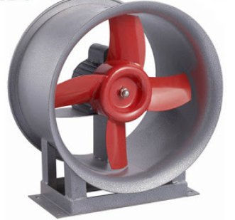
Propeller Fans
Propeller fans are belt driven or direct driven fans consisting of housing, fan blades, hub, orifice ring, bearings, motor, drive assembly and accessories.
a. Housing shall be galvanized steel sheet with flanged edges and integral orifice ring with baked enamel finish coat applied after assembly.
b. Fan wheels shall be formed steel blades riveted to heavy gage steel spider bolted to cast iron hub or replaceable, cast aluminum or extruded aluminum, airfoil blades fastened to cast aluminum hub; factory set pitch angle of blades.
c. Belt driven drive assembly shall be resiliently mounted to housing, statically and dynamically balanced and selected for continuous operation at maximum rated fan speed and motor horsepower, with final alignment and belt adjustment made after installation.
(i) Service factor based on fan motor shall be 1.4.
(ii) Fan shaft shall be turned, ground, and polished steel; keyed to wheel hub.
(iii) Shaft bearings shall be permanently lubricated, permanently sealed, self-aligning ball bearings with an AMBA 9, L10 life of 100,000.
(iv) Pulleys shall be cast iron with split, tapered bushing; dynamically balanced at factory.
(v) Motor pulleys shall be adjustable pitch for use with motors through 5 hp; fixed pitch for use with motors larger than 5 hp. Pulleys shall be selected so pitch adjustment is at the middle of adjustment range at fan design conditions.
(vi) Belts shall be oil resistant, non-sparking, and non-static; matched sets for multiple belt drives. (vii) Belt guards shall be fabricated of steel for motors mounted on outside of fan cabinet.
d. Accessories, when required by fan application:
(i) Gravity shutters shall be aluminum blades in aluminum frame; interlocked blades with nylon bearings.
(ii) Motor side back guard shall be galvanized steel, complying with OSHA specifications, removable for maintenance.
(iii) Wall sleeve shall be galvanized steel to match fan and accessory size.
(iv) Weathershield hoods shall be galvanized steel to match fan and accessory size.
(v) Weathershield front guards shall be galvanized steel with expanded metal screen.
(vi) Variable speed controllers shall be solid-state control to reduce speed from 100 percent to less than 50 percent.
(vii) Disconnect switch shall be non-fusible type, with thermal-overload protection mounted inside fan housing, factory wired through an internal aluminum conduit.