This article is about Impulse Line Installations of Instrumentation transmitters, which describes different methods. In this article, as instrument and control engineer, you will learn about transmitter installation with impulse line of different services like Wet Gas Applications, Steam, What to do if there is two phase flows, Close coupling transmitter installation and impulse line purging.
Impulse Line Installations for Engineers
The positioning of the secondary instrument concerning the primary instrument imply that gas-filled impulse lines should have an upward slope from the pressure tappings to the transducer, while liquid-filled lines should slope downward. ISO/CD 2186:2004 specifies that impulse lines should be installed in a manner where the slope is in one direction only. If a change in the direction of the slope is unavoidable, then only one such change should be made. In such cases, it becomes necessary to incorporate a liquid trap at the lowest point and a vapor vent at the highest point. The minimum recommended slope for self-draining or self-venting is 8 percent.
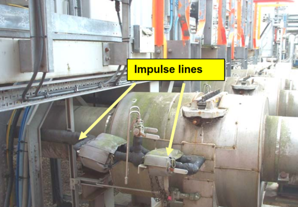
For instance, Figures 3 and 4 provide examples of impulse lines used with dry natural gas. In Figure 3, the impulse lines extend from an orifice plate with horizontal tappings to an instrument room. These lines are configured with an upward slope towards the instrument room and are equipped with insulation.
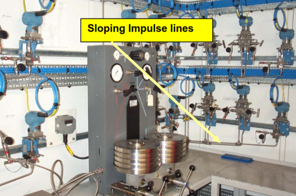
In Figure 4, which provides a view of the interior of the instrument room, you can observe that the impulse lines are configured to slope upward towards the differential-pressure transducers. This design ensures that any liquids that might form within the lines will naturally flow downward. Given that the cabin maintains a consistent temperature above the dew point of the gas in the impulse lines, there is no requirement for insulation in this setup. Additionally, the transmitters are calibrated directly within their installed positions.
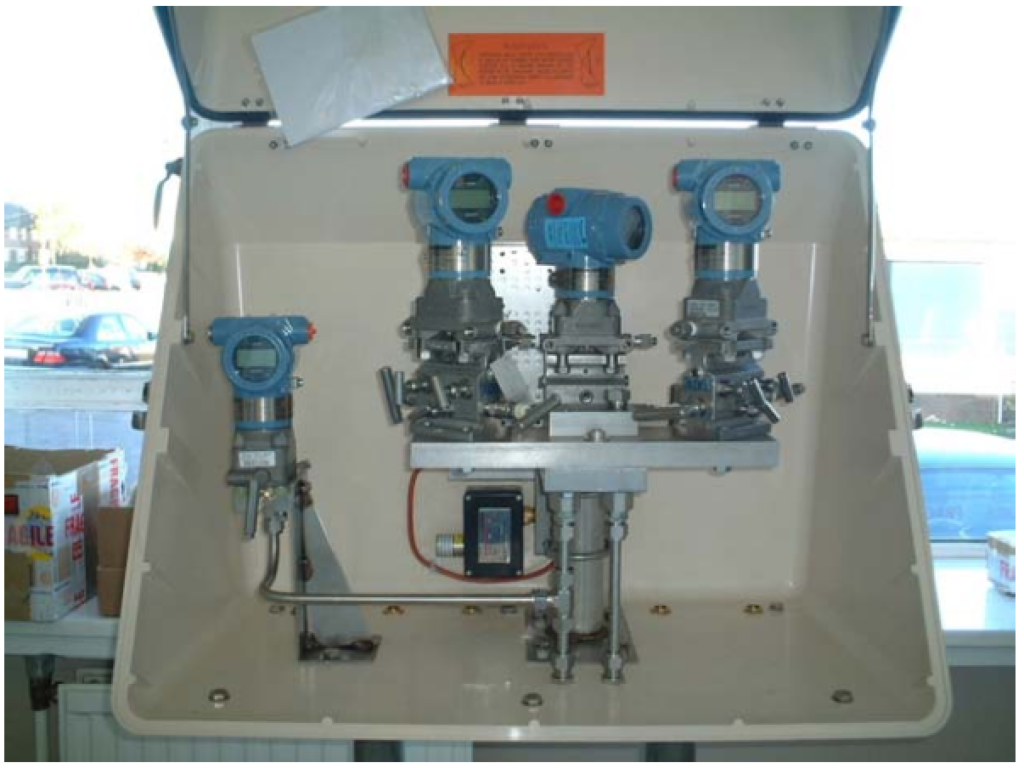
In Figure 5, we can observe an enclosure housing three differential-pressure transmitters and one static-pressure transmitter. Within the enclosure, a heater is situated (located behind the transmitters in the center of the image). The three differential-pressure transmitters are affixed to a mono-block.
In scenarios where high-static calibration is conducted off-site, and on-site footprinting is standard practice, smaller enclosures present no issues. This is because when the transmitters are mono-block mounted, the entire block containing the mounted transmitters can be removed for remote calibration. Footprinting can then be executed in-situ on-site with minimal inconvenience. Furthermore, the mono-block configuration contributes to stabilizing temperature conditions.
For systems involving multiple connected transmitters via pipework, it is prudent to maintain minimal distances between the transmitters. In some gas systems where three or more transmitters are employed, and the spacing between transmitters is approximately 1 meter, gas noise can become problematic. The signal from the end transmitter may reflect in a manner that either increases or decreases the signal strength at the first transmitter. This issue can create challenges when assessing the accuracy of measured differential pressures through comparisons between pairs of transmitters and setting alarms. Consequently, close coupling between such transmitters is highly desirable, as depicted in Figure 5.
The recommended slopes for impulse lines in vertical pipe meters are generally consistent with those for horizontal meters.
However, when utilizing liquid-filled lines for measuring the flow of vapor or gas within a vertical pipe, a disparity in liquid head between the tappings becomes apparent. Consequently, there exists a pressure difference between the tappings under static conditions, which can be addressed through one of two methods:
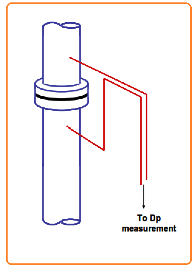
- The lower impulse line is directed upward before making a horizontal turn at the same height as the upper impulse line. Subsequently, both lines are formed to descend toward the secondary device. This arrangement equalizes the liquid head above the secondary device in the two impulse lines and eliminates the need for a correction to the instrument calibration.
- Both impulse lines exit the tappings horizontally and then curve downward towards the secondary device. In this case, the zero point of the secondary device must be adjusted to account for the difference in liquid head above the secondary device.
Option 1 is illustrated in Figure 6 below.
ISO/CD 2186:2004 is a valuable resource for understanding recommended impulse-line configurations, complete with helpful diagrams. It should be your primary reference when seeking information on this topic. The upcoming version, currently at the Committee Draft stage, is expected to enhance the standards provided in the 1973 version.
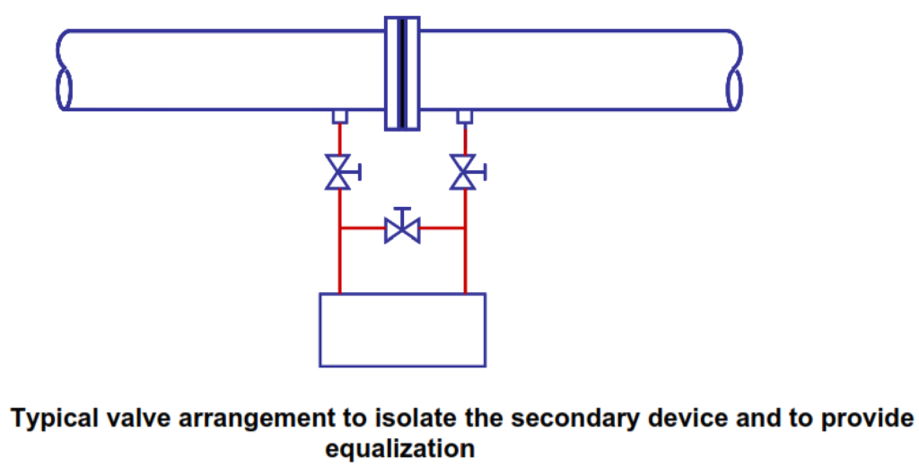
The standard includes a practical section on isolation valves, which are typically necessary in real-world applications. However, their use may conflict with the preference for minimizing joints in the impulse lines and avoiding changes in diameter. It’s worth noting that certain valve choices are better than others; it’s advisable to steer clear of globe valves with vertical stems that might create pockets of gas or liquid. In many cases, it’s desirable to have the option to connect the high- and low-pressure sides of the differential-pressure transducer so that the signal can be obtained at line pressure without any differential pressure, often referred to as performing a high-static zero check (as depicted in Figure 2).
While installations deviating from the recommended standards are possible, they typically entail more maintenance. For instance, if the transducer is situated below the pressure tappings in gas applications, drain pots and valves become necessary. Conversely, when the transducer is located above the pressure tappings in liquid applications, vent valves, at the very least, are required.
In certain installations, there may be a need to “rod out” the impulse lines, particularly in steam flow applications where dirt can be a significant issue. In addition to the requirements mentioned above, provisions for draining or venting the impulse lines might be necessary, both immediately after installation (e.g., after hydrostatic testing) and during ongoing maintenance. It’s important to note that the specifications for the impulse line piping may differ from those for the process piping due to the more limited temperature conditions in the impulse lines.
For steam flow applications, plugged tees in the impulse lines may be essential to facilitate filling the impulse lines with water during startup.
Specific Guidelines for Wet Gas Applications
The Department of Trade and Industry Licensing and Consents Unit provides valuable Guidance Notes for Petroleum Measurement under the Petroleum (Production) Regulations, last updated in December 2003 (Issue 7). These guidelines offer specific insights, particularly regarding wet gas applications, and can be accessed at www.flowprogramme.co.uk/clubs/ogfg.
One key concern in these applications is the likelihood of liquid drop-out in impulse lines due to the cooling of gas as it exits the meter stream and approaches ambient temperatures. In severe cases, hydrates may even form. To mitigate measurement errors arising from the presence of liquids or hydrates in impulse lines, the Guidance Notes reiterate general recommendations. They emphasize that impulse lines should be kept as short as possible and inclined upward to facilitate the drainage of entrained liquids.
Furthermore, the Notes suggest additional measures to counteract liquid or hydrate accumulation, such as insulating the impulse lines and applying trace heating. Operators are encouraged to consider placing transmitters, and if feasible, impulse lines within a heated and sealed enclosure.
The Notes also propose the use of catchment pots within the impulse lines, which can be effective at capturing liquids. However, it’s crucial to drain these catchment pots regularly to prevent excessive liquid accumulation. It’s worth noting that catchment pots may not be as effective in un-manned installations experiencing significant liquid drop-out in impulse lines.
For wet gas applications, the Notes recommend orienting the meter horizontally, positioning the pressure tappings at the 12 o’clock position. This orientation minimizes the potential for liquid entrainment in the tappings or impulse lines and keeps the tappings as distant as possible from the bulk of the liquid, especially in cases of stratified or annular flow regimes.
Specific Guidelines for Steam
Impulse lines in steam flow applications are typically designed to remain filled with condensate at all times. Achieving this is often done through a siphon arrangement or by incorporating a low point in the impulse lines where condensate collects. This design effectively insulates the transducer from the steam. Additionally, seal pots (also known as condensate pots) are commonly integrated into the setup, and provisions are made for venting, flushing the lines, and filling them with water.
The report recommends insulating impulse lines and providing trace heating to prevent condensate from freezing in cold weather conditions. In some cases, glycol may be added to the condensate in the impulse lines for similar reasons. To ensure a prompt response from pressure transducers and prevent sluggishness caused by gas bubbles in the impulse lines, purging the lines to eliminate trapped air is advised.
Certain manufacturers also suggest the use of condensate or seal chambers for steam flow, particularly when the instrument displaces a substantial volume of liquid during measurement changes. Seal chambers are small pressure vessels mounted at the top of the liquid-filled impulse line. Each chamber serves as a reservoir within the impulse line, ensuring minimal elevation changes in response to large volume variations. This design prevents seal liquid from being discharged into the process line and prevents measurement errors caused by elevation shifts in the wet-leg liquid. It’s worth noting that modern transducers with minimal volumetric displacement typically do not require seal chambers. Spirax Sarco, for instance, recommends condensate pots only for superheated steam applications and advises against the configuration shown in Figure 6. They always recommend the removal of the static-head offset using the secondary instrument.
Figure 7 illustrates the use of seal pots.
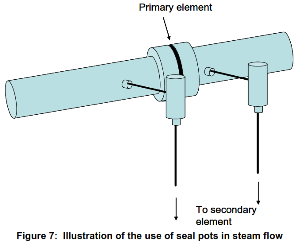
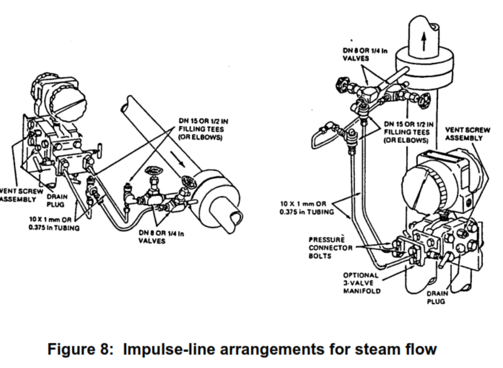
Figure 8, sourced from Reference 3 (also referenced in Mottram et al.), depicts common arrangements for steam flow in both horizontal and vertical pipelines. Additionally, Figure C.5 of ISO/CD 2186:2004 provides valuable insights into this subject.
Condensing or Evaporating Fluids
In the realm of flow measurement for fluids nearing their bubble or dew point, the primary objective remains the consistent maintenance of both impulse lines, ensuring they are consistently filled with either gas or liquid across all operational and environmental conditions.
The guidance outlined in Section [Specific Guidelines for Wet Gas Applications], initially designed for steam flow, can be broadly applied to any condensable vapor with a dew point exceeding the ambient temperature. Under such circumstances, impulse lines will naturally tend to fill with liquid. However, in alternative applications, the choice of approach may vary based on factors such as dew and bubble points, ambient temperature, the condensable vapor’s mass fraction, and the utilization of trace heating or cooling. For instance, when there’s a possibility of condensation occurring only in small quantities for a vapor component, it may be more prudent to adhere to the recommendations suited for gas flow.
In cases where the ambient temperature consistently remains above the dew point, it is advisable to strictly follow the recommendations for gas flow.
Flow measurement of a liquid prone to evaporation at ambient temperatures can present similar challenges. To prevent boiling of the liquid within the impulse lines, insulation may be necessary. Conversely, when ambient temperatures significantly surpass the bubble point, it may be more fitting to design the system with vapor in mind for the impulse lines.
Read Also: Impulse Line Blockages: Causes, Effects, and Solutions
TWO-PHASE FLOW
In situations involving two-phase flows, it is common practice to design impulse lines to be filled with either liquid or vapor, depending on the flow characteristics. This approach aligns with the principles discussed in previous sections, including the need to prevent condensation in vapor-filled lines and boiling in liquid-filled lines, which may necessitate the use of trace heating or insulation.
The positioning of pressure tappings should be carefully considered, taking into account the expected flow pattern in two-phase conditions. For instance, in scenarios featuring stratified flow and gas-filled lines, it is advisable to place the tappings on the top of the pipe to ensure accurate measurements.
Dealing with pulsating two-phase flows presents its own set of challenges, particularly due to the periodic injection of gas bubbles into liquid-filled impulse lines.
When installing a flow meter in a vertical pipe, special attention is required because the fluid in the meter line between the tapping points may have a different density compared to the fluid in the impulse lines. Correcting for this density difference involves calculating the mean two-phase density within the pipe line, which introduces a level of uncertainty. Moreover, despite the intention to use single-phase fluids in impulse lines, practical conditions often lead to two-phase fluid states. Consequently, it has been found that in multiphase flow applications, a horizontal orientation of a Venturi tube is preferable.
In cases where maintaining a single-phase fluid in the impulse lines proves challenging, especially when the dew or bubble point is near ambient temperatures, opting for a horizontal meter configuration with the secondary instrument level with the primary instrument may be a more favorable choice. This arrangement helps minimize uncertainties related to the static head between the tapping points and the secondary instrument.
IMPULSE LINE PURGING
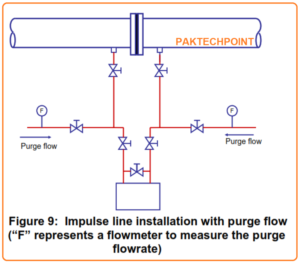
One effective solution to address issues related to impulse line blockage, gas bubbles in liquid lines, and liquids in gas lines is to implement a continuous purge flow through these lines. This involves purging impulse lines with either a dry gas to prevent the entry of liquids or vapors or using a non-freezing liquid to keep the process fluid out. To ensure proper operation, it is crucial to maintain equal lengths of purging for both lines and to equalize the purging flow rates. The diagram below (Figure 9) illustrates a typical setup featuring continuous impulse line purging.
However, this approach comes with certain drawbacks, including the need for additional hardware and piping and the requirement for precise control of the purge flow rate. Special attention must be paid to ensure that the frictional pressure drop caused by the purge flow remains minimal, which may necessitate selecting a larger internal diameter for the impulse line.
In certain cases, continuous liquid purging has been recommended as a method to prevent undesirable effects resulting from the pumping of vapor bubbles into liquid lines, particularly in pressure measurement applications within two-phase flows, especially in research settings.
CLOSE COUPLING
Recently, several transmitter manufacturers have introduced innovative transducer mounting arrangements that involve directly attaching the differential-pressure transducer to the meter pipe. This approach eliminates the need for conventional impulse lines, although there remains a section of tapping between the pipe and the differential-pressure transducer. This mounting arrangement offers significant advantages, simplifying the piping system and, most importantly, reducing the number of joints, thereby minimizing potential leak paths at threaded connections and compression fittings.
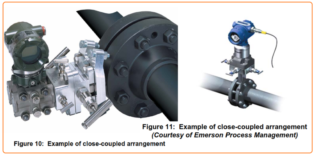
Furthermore, this arrangement reduces the necessity for insulation or trace heating and mitigates errors caused by variations in fluid densities within different lines. It also alleviates issues related to liquid drop-out or gas break-out in the impulse lines when there are significant temperature differences between the ambient conditions and the line temperature. When short impulse lines are required due to pulsations, close coupling provides the shortest possible lines and ensures a rapid response.
However, there are trade-offs to consider. Close coupling necessitates positioning the transmitters in small enclosures near the meter, rather than in larger cabins at a greater distance. While this arrangement may pose challenges for in-situ calibration and may be less appealing to operators, the small enclosures typically offer shelter, if not precise temperature control. It’s worth noting that modern transmitters are less sensitive to temperature changes than their earlier counterparts.
It’s important to mention that the use of impulse lines may still be necessary when the line temperature falls outside the suitable range for the pressure transducer.