In instrumentation and control systems, an impulse line is a small-diameter tube or pipe that connects a process fluid to a pressure transmitter or other measurement instrument. The primary purpose of an impulse line is to transmit the pressure of the process fluid to the sensing element of the instrument, allowing it to accurately measure and monitor the pressure, temperature, or other relevant parameters of the process.
Following are the points to understand about impulse lines in instrumentation:
- Pressure Transmission: Impulse lines are used to convey the pressure of the process fluid from the point where the measurement is required to the pressure sensing element of the instrument. This helps protect the sensitive instrument from direct contact with the potentially corrosive, hot, or dangerous process fluid.
- Material Selection: The material used for impulse lines is typically chosen based on the properties of the process fluid and the conditions it will be exposed to. It’s essential to select materials that are compatible with the process fluid to prevent corrosion, contamination, or damage to the instrument.
- Length and Diameter: The length and diameter of the impulse line can impact the accuracy of the measurement. Longer or narrower impulse lines can introduce delays or inaccuracies in the pressure readings due to the damping effect of fluid flow.
- Purging and Drainage: Impulse lines may need to be designed with provisions for purging and draining to prevent the accumulation of fluids, gases, or contaminants that could affect measurement accuracy. This is especially important in applications with changing process conditions.
- Protection: In some cases, impulse lines may require additional protection, such as heat tracing or insulation, to maintain the temperature of the process fluid and prevent freezing or condensation issues that can affect measurement accuracy.
- Maintenance: Regular inspection and maintenance of impulse lines are essential to ensure that they remain in good condition and do not introduce errors into the measurement process. This may include cleaning, flushing, and replacing worn components.
Impulse lines play a crucial role in ensuring the accuracy and reliability of measurements in industrial processes where pressure, temperature, or other parameters need to be monitored. Proper design, material selection, and maintenance are essential to minimize measurement errors and ensure safe and efficient operation.
Impulse line in instrumentation
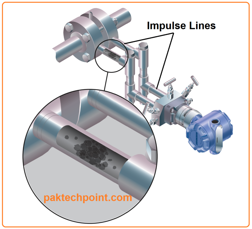
Pressure transmitters are essential components used in various industrial applications, including pressure, level, and flow measurements. However, they are typically not directly connected to the pipes or vessels containing the process fluid. Instead, small-diameter tubes or pipes, often referred to as impulse lines, are employed to convey the pressure signal from the process to the transmitter.
In certain situations, these impulse lines can encounter issues, such as blockages caused by solids or frozen fluids in cold environments. These blockages can effectively disrupt the transmission of pressure signals (as illustrated in Figure 1). Alarmingly, a survey conducted in Europe estimated that approximately 60 percent of heat trace systems designed to prevent freezing in impulse lines are not functioning correctly [reference needed]. Unfortunately, users often remain unaware of these blockages. This lack of awareness arises because the pressure reading at the time of blockage is trapped within the system, causing the transmitter to continue providing the same output signal as before the blockage occurred. It’s only when actual process changes take place, and the pressure transmitter’s output remains unchanged, that someone may recognize the existence of a blockage.
This situation is a common challenge in pressure measurement applications, and it underscores the need for diagnostic features capable of detecting and alerting users to blocked impulse lines.
Impulse Line Diagram Explanation
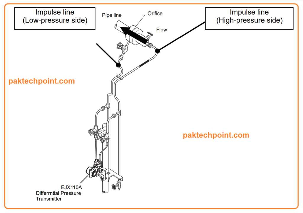
An impulse line is a small-gauge pipe that is used to connect a point in a pipe in which the pressure is measured by an instrument. Impulse lines are commonly used in flow measurement using a primary device such as an orifice plate, nozzle or Venturi meter. Impulse lines connect the upstream and downstream (or throat) points of the meter to a secondary device, such as a differential pressure transmitter, for measuring the pressure difference
Factors Affecting Impulse Lines
Some of the factors that affect the design and performance of impulse lines are:
- Impulse-line diameter and length.
- Location of the secondary device relative to the primary device.
- Routing of the impulse lines between the primary and secondary devices, including the slope
- Location of pressure tappings.
- Effects of ambient temperature, temperature gradients and fluctuations, and the associated need for heating or insulation.
- Fluid in the impulse lines.
- Valves and connections for venting and draining.
- Isolation valves.
- Avoiding impulse-line blockages.
Impulse lines can cause a number of problems that can lead to inaccurate measurements, such as:
- Scaling or corrosion of the impulse line material
- Freezing or vaporization of the fluid in the impulse lines
- Leakage or clogging of the valves or connections
- Gas noise or signal reflection in the impulse lines
To avoid these problems, it is recommended to use appropriate material selection, standardization, calibration, and maintenance practices for impulse lines.
Problems Caused by Impulse Lines with Pictures:
The use of impulse lines can introduce various challenges and potential sources of measurement inaccuracies. These problems can stem from the following factors:
- Damping and Resonances: Impulse lines may dampen the pressure signal or create resonances, especially when transient measurements are needed or when the lines have unequal lengths.
- Blockage: Blockages within impulse lines can impede the flow of the process fluid, leading to incorrect measurements.
- Leakage at Couplings: Leaks at the connection points or couplings of impulse lines can compromise measurement accuracy.
- Temperature Variations: Variations in temperature between two impulse lines can result in differences in fluid density, affecting measurement consistency.
- Composition Discrepancies: When the fluid within the impulse lines differs in composition from the fluid in the main pipeline, it can pose challenges, especially in vertical meters where gravity head corrections are required.
- Condensation: In cases where impulse lines are intended to be filled with gas, condensation can occur, potentially interfering with measurements.
- Gas Trapping or Boiling: Impulse lines designed for liquid may inadvertently trap gas bubbles or experience boiling of a liquid with a bubble point below the ambient temperature, both of which can impact measurement accuracy.
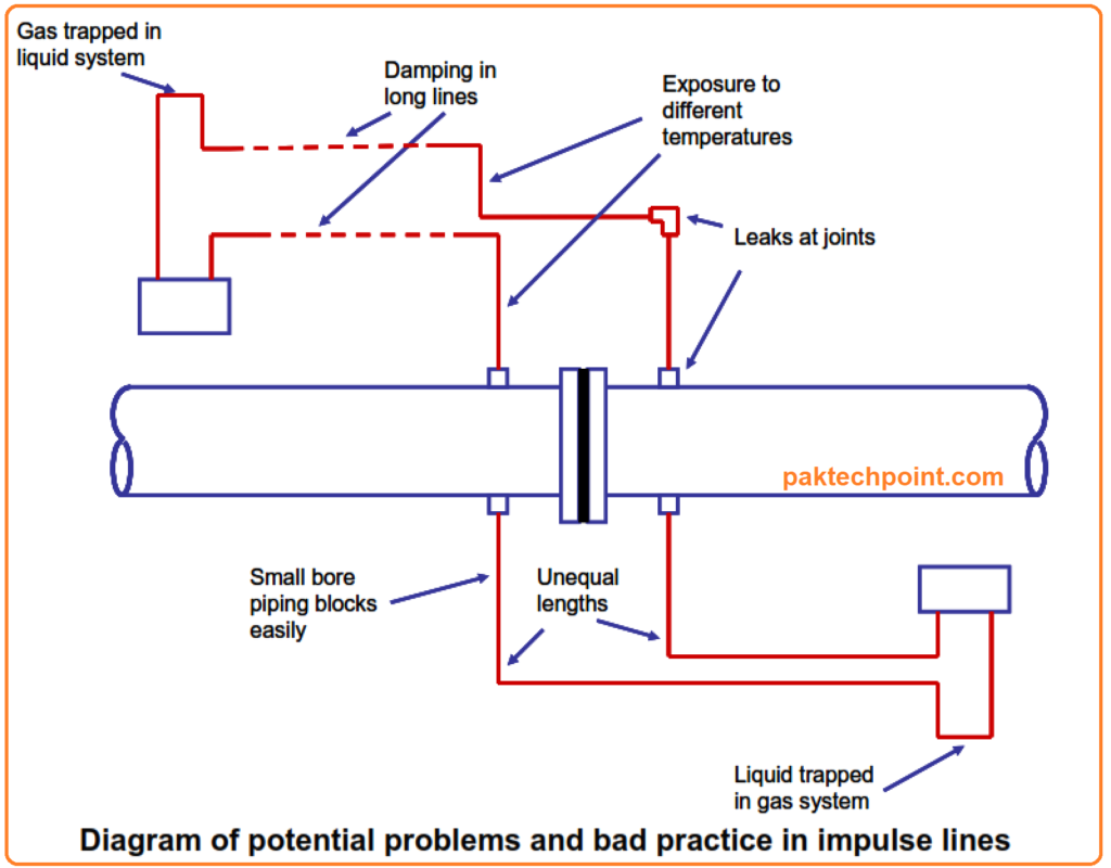
These issues highlight the need for careful design, maintenance, and consideration of various factors when using impulse lines in industrial instrumentation to ensure accurate and reliable measurements.
Impulse Line Blockage Detection (ILBD)
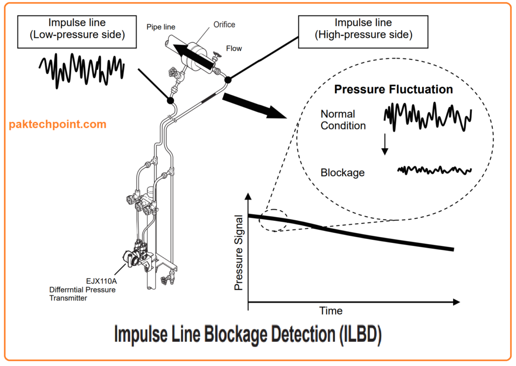
During fluid flow measurement through a pipeline, it’s not uncommon for the impulse line to become obstructed by solid particles or frozen fluids. This obstruction can be exacerbated by pressure fluctuations generated by pumps and other machinery within the system. To address this issue, a differential pressure transmitter is employed to measure both the differential pressure and the variations caused by these process-related fluctuations.
By analyzing and extracting the fluctuation component from both the differential pressure and static pressure signals, it becomes possible to discern the condition of the impulse line. This extracted component, indicative of the process fluctuations, serves as a valuable indicator for assessing the extent of impulse line blockage. This function, often referred to as Impulse Line Blockage Detection (ILBD), empowers operators to identify potential blockage conditions well before they can disrupt the control of flow and pressures within the plant.
While the primary purpose of a differential pressure transmitter is to accurately measure differential pressure based on the flow conditions, its ability to capture and analyze process fluctuations provides a foundation for critical diagnostics like ILBD. As depicted in Figure 1, a notable reduction in transmitted pressure fluctuations occurs when the high-pressure-side impulse line becomes blocked. This principle holds true for applications involving level and pressure measurements as well.
Impulse line vs Capillary tube
Following table is comparison of impulse lines and capillary tubes:
| Aspect | Impulse Line | Capillary Tube |
|---|---|---|
| Purpose | Transmits pressure signals from the process to the instrument. | Transmits pressure or temperature signals from the process to the instrument. |
| Application | Used in pressure, level, and flow measurement applications. | Used primarily in temperature measurement applications. |
| Diameter | Typically larger in diameter compared to capillary tubes. | Characterized by smaller inner diameters. |
| Material | Material selection depends on the process fluid and environmental factors. | Made of materials compatible with temperature measurement, often stainless steel. |
| Blockage and Contamination | Prone to blockages by solids, debris, or freezing in cold environments. Can also be contaminated. | Less prone to blockages but can still be affected by contaminants. |
| Temperature Effects | Susceptible to temperature fluctuations that can affect measurement accuracy. | Used to measure temperature and are less affected by temperature variations. |
| Purpose of Use | Primarily used for pressure measurement. | Primarily used for temperature measurement. |
| Common Issues | Blockages, contamination, corrosion, condensation, temperature effects. | Contamination, temperature effects, and response time limitations. |
| Maintenance | Requires regular inspection, cleaning, and maintenance to ensure accuracy. | Requires periodic calibration and maintenance. |
| Typical Instruments | Pressure transmitters, pressure gauges. | Temperature sensors, thermocouples, resistance temperature detectors (RTDs). |
| Flexibility | May require some flexibility in design and material choice to accommodate pressure measurement needs. | Often rigid and not designed for flexibility. |
| Special Considerations | Often used in fluid-filled systems. | Typically used in systems where temperature measurement is critical. |
Impulse Lines Notes for Engineers
Following are important points for Instrument and control engineers to remember.
- Impulse Line Condition: Accurate blockage detection is challenging if the impulse line is nearly blocked when the reference value is established. Both the high and low-pressure-side impulse lines should be cleaned before obtaining a reference value.
- Air Bubbles: Ensure that all air bubbles are thoroughly purged from the system before obtaining a reference value for blockage detection.
- Stable Flow: It’s crucial to have stable flow conditions when obtaining a reference value for blockage detection.
- Configuration Software: FOUNDATION fieldbus compatible configuration software, such as PRM and FieldMate, can be used to configure blockage detection with an EJX differential pressure/pressure transmitter. No additional specialized measuring device is necessary since the EJX can establish a reference value.
- Pressure Fluctuation Amplitude: To effectively detect blockages, the pressure fluctuation amplitude in fluids must be sufficiently large. In cases like level or pressure measurement or when dealing with gas media, the amplitude might be too small for accurate blockage detection.
- Flow Variations: If the flow significantly increases or decreases (more than 25%) after obtaining a reference value, it’s advisable to obtain a new reference value under more stable flow conditions. Otherwise, blockage detection may not function correctly.
- Simulated Testing: To assess blockage detection ability, the appropriate manifold should be mounted on the impulse lines, and it must be operated to simulate and detect a blockage. Without this simulation, it’s impossible to determine if blockage detection is functional.
- Consider Operating Conditions: False alarms for impulse line blockage can occur in certain scenarios. For instance, in flow measurement, false alarms may arise when the pressure drops to the diagnostic range limits, or when flow decreases even with constant pressure. It’s essential to consider the specific operating conditions before taking action based on a blockage alarm.
- Level Measurement: Similar to flow measurement, false alarms can occur in level measurement when fluid flow into or out of a tank stops, the tank’s agitator is shut down, or a source of pressure variation in a sealed tank is shut down.
- Process Variability: ILBD relies on statistical values derived from pressure fluctuations, and its accuracy can vary with process conditions. It’s important to note that 100% accurate detection of all blockages under all conditions is not guaranteed when using the ILBD function with an EJX differential pressure/pressure transmitter. The effectiveness of blockage detection depends on the specific process conditions.
Read Also: General Instrumentation Accessories Installation Design Notes