The design of a typical installation for differential-pressure flow measurement entails careful consideration of several crucial factors concerning the impulse lines:
- Impulse-Line Diameter and Length: Determining the appropriate diameter and length of the impulse lines to ensure accurate measurement.
- Location of Secondary Device: Positioning the secondary measurement device in relation to the primary device for optimal performance.
- Routing of Impulse Lines: Planning the path and slope of the impulse lines that connect the primary and secondary devices.
- Location of Pressure Tappings: Identifying the precise locations for pressure tappings to capture the necessary data accurately.
- Ambient Temperature and Temperature Variations: Accounting for the effects of ambient temperature, temperature gradients, and fluctuations, and considering whether heating or insulation is necessary.
- Fluid in Impulse Lines: Ensuring that the fluid within the impulse lines is compatible with the process and won’t introduce measurement errors.
- Valves and Connections for Venting and Draining: Installing valves and connections to facilitate venting and draining of the impulse lines, preventing blockages and maintaining measurement accuracy.
- Isolation Valves: Including isolation valves for maintenance and servicing purposes, allowing the system to be shut down when necessary without affecting the overall process.
- Preventing Impulse-Line Blockages: Implementing strategies to prevent blockages within the impulse lines, which can lead to incorrect measurements.
Geometry
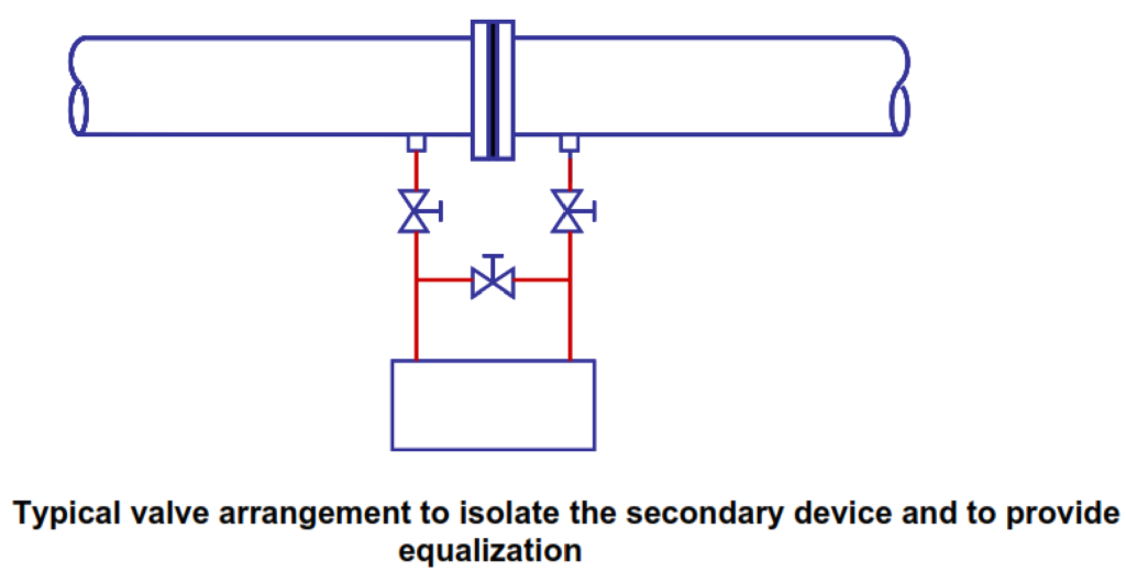
To address the issues mentioned earlier in previous article, it is advisable to keep impulse lines as short as possible. However, some limitations must be considered, such as the need to isolate a secondary device from high-temperature pipeline fluids and the necessity of incorporating valves between the primary and secondary devices. These valves enable the removal or replacement of the secondary device and the creation of a path between high- and low-pressure sides without any differential pressure. Below Figure illustrates a typical arrangement, and additional valves, often organized in a single manifold, may be necessary for tasks like draining, venting, or calibration.
Similarly, it is generally preferable to choose the smallest internal diameter for impulse lines, although practical constraints must be taken into account. Factors like the risk of damage and blockages, capillary effects, and the need to prevent trapped bubbles in liquid lines or trapped liquid in gas-filled lines may limit the smallest feasible diameter. Typically, impulse-line diameters within the range of 4 mm to 25 mm are employed. The smallest sizes are typically used for applications involving unsteady flow or research purposes.
The international standard ISO 2186 is currently undergoing revision, with the existing draft (ISO/CD 2186:2004) recommending an internal diameter of at least 6 mm and preferably 10 mm if there’s a likelihood of condensation or gas bubbles being released from a liquid. For industrial process applications where reliability is a top priority, it suggests a minimum internal diameter of 10 mm. In general, a maximum internal diameter of 25 mm is recommended.
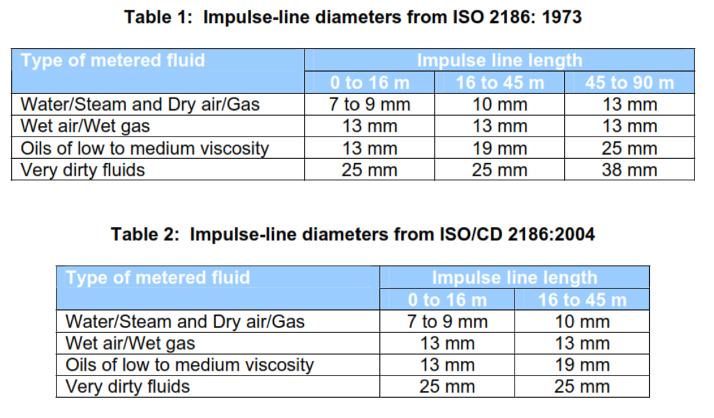
ISO 2186:1973, which is still in force, contains a table specifying very long impulse-line lengths and large impulse-line diameters, provided as Table 1. In ISO/CD 2186:2004, the largest lengths and diameters have been omitted, and Table 2, shown below, is included as an informative annex. It is introduced with the statement ‘It is always recommended that the shortest possible impulse line lengths be used. Where it is not possible to conform with this, guidance on the preferred line diameter may be obtained from Table D.1’ (equivalent to Table 2).
When it becomes necessary to employ lengthy impulse piping, it becomes crucial to establish robust support systems for the piping. This is essential to eliminate the risk of damage caused by vibration. In particular, it’s important to ensure that the natural frequency of the longest unsupported section of the piping does not align with any potential frequencies that could induce vibrations within the system.
Fluid
In various applications, the fluid present in the impulse lines serves specific purposes. For instance, in cases like measuring the flow of a non-condensing gas at ambient temperatures, the fluid within the impulse lines corresponds to the fluid being metered. However, in scenarios like measuring steam flow, where the steam’s saturation temperature significantly exceeds ambient conditions, it can be advantageous to have the fluid in the impulse lines in its liquid phase.
It is absolutely critical to prevent the occurrence of gas or vapor bubbles within liquid-filled lines and to avoid liquid presence within gas-filled lines.
In certain applications, such as steam flow involving condensate (liquid water) within the impulse lines, it may be necessary to fill these lines before starting up the measurement process.
Temperature Effects
The pressure head within an impulse line is directly influenced by the fluid’s density, which, in turn, is sensitive to changes in fluid temperature. Hence, it’s considered good practice to ensure that both impulse lines are exposed to the same ambient temperatures. For instance, having one impulse line exposed to direct sunlight while the other remains in the shade would be considered poor practice. To address this, it’s recommended to physically connect or tie together the impulse lines, even if they are already insulated.
Insulation and protection from solar heating become especially crucial when the impulse lines contain a liquid that is near its bubble point. Furthermore, using insulation helps mitigate fluctuations in ambient temperature, which can have a bearing on the stability of the pressure head within the impulse line.
To provide an idea of the impact of having disparate temperatures in the impulse lines, consider a scenario where both lines contain water, with one at 20°C and the other at 30°C. If there is a 2-meter difference in height between the pressure tappings and the differential-pressure transducer, it would result in a measurement error of 49 Pascal (Pa) in the recorded differential pressure.
Location of Secondary Instrument
In gas-filled impulse lines, it is advisable to position the secondary instrument above the primary instrument. This setup aids in the effective drainage of any liquid that might accumulate in the lines. Conversely, for liquid-filled impulse lines, it is recommended to place the secondary instrument below the primary instrument. This configuration facilitates the venting of any gases that might be present.
In cases where liquid-filled lines are used, it is of paramount importance to ensure that the liquid levels in the two impulse lines are equalized or otherwise compensated to maintain accurate measurements.
However, when measuring oil, especially when there is a risk of contamination with water, the conventional arrangement of placing the transducer below the tappings may not be suitable. In such instances, it might be more suitable to position the transducer above the tappings and incorporate additional measures to address the potential presence of gas in the impulse lines. This issue is not unique to oil and water but can arise with other immiscible pairs of liquids as well.
Location of Pressure Tappings
The guidelines outlined in ISO/CD 2186:2004 for horizontal pipes are condensed into Table 3. The fundamental principle behind these recommendations is that in gas- or vapor-filled impulse lines, it is advisable for them to incline upwards to facilitate the drainage of any liquid. Conversely, in the case of liquid-filled lines, having tappings positioned below the center line can lead to the accumulation of solid substances, while tappings situated above the center line may accumulate non-condensing gases.
| Fluid | Pressure Tapping Location |
| Dry gas | Between the top of the pipe and the horizontal centre line |
| Wet gas | Between the top of the pipe and the horizontal centre line, but so that the tappings are self-draining |
| Liquid | On the horizontal centre line |
| Condensing vapour | On the horizontal centre line |
For steam flow within horizontal pipelines, it may also be acceptable to position tappings between the horizontal center line and 45 degrees below the horizontal.
In vertical pipelines, there are no specific constraints regarding the radial placement of the pressure tappings.
Read Also: Impulse Line Blockages: Causes, Effects, and Solutions