This article details the design, construction and testing of low voltage electric motors 150 kW (200 HP) and below used to drive mechanical equipment in industrial installations. The typical motor described in this article is a horizontal foot mounted induction motor with standard short shaft. Main keywords for this article are Induction Motors Design Requirements below 150 kW in Plants, How Induction Motor Starts, Induction Motor Control, Working of Induction Motor, Induction Motor Testing.
Induction Motors Design Requirements below 150 kW in Plants
Induction Motor References
American National Standards Association / Institute for Electrical and Electronics Engineers (ANSI/IEEE)
IEEE 841 Standard for Petroleum and Chemical Industry – Premium Efficiency, Severe Duty Totally Enclosed Fan-Cooled (TEFC) Squirrel Cage Induction Motors – up to and including 370 kW (500 hp).
IEEE112 Test Procedure
American Bearing Manufacturers Association (ABMA)
B9 Load Rating and Fatigue Life of Ball Bearings
American Petroleum Institute (API)
RP 540 Electrical Installations in Petroleum Processing Plants
661 Air-Cooled Heat Exchangers for General Refinery Service
National Electrical Manufacturer’s Association (NEMA)
MG-1 Motors and Generators
NEMA 4 Cast Iron Terminal Boxes
National Fire Protection Association (NFPA)
NEC (NFPA 70) National Electrical Code
Underwriters Laboratories (UL)
UL 674 Electric Motors and Generators for use in Division 1 Hazardous (Classified) Locations
Working of Induction Motor
Main keywords for this article are Induction Motors Design Requirements below 150 kW in Plants, How Induction Motor Starts, Induction Motor Control, Working of Induction Motor, Induction Motor Testing.
Induction Motor Control
How Induction Motor Starts
https://www.youtube.com/watch?v=mN2-xDvguto
Induction Motors Design Requirements
- Motors for use in Division I and Division II hazardous locations shall be UL 674 approved.
- Motors for fin fan (Air Cooled Exchanger) service shall conform to API 661.
- Motors exposed to salt laden air shall be of the totally enclosed type and of severe duty type construction.
- Motors shall be specified with torque requirements for the specific application of the driven equipment. When motors are furnished with the driven equipment as a package, the torque and speed requirements shall be as stipulated by the driven equipment vendor.
- Motors shall operate successfully at rated load, with rated frequency even if voltage variation is ±10 percent of the rated voltage.
- Motors shall operate successfully at rated load, with rated voltage even if frequency variation is ±5 percent of the rated frequency.
- Motors shall operate successfully at rated load with combined variations of rated voltage and frequency not exceeding ±10 percent. Frequency variation not to exceed ±5 percent.
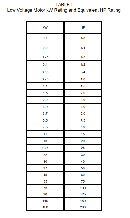
- Motor conversion from kW to HP ratings shall be in accordance with Table I of this specification. When the power requirement of the driven equipment falls between two of the standard ratings, the larger power rating shall be used for the selected motor.
- Motors shall be equipped with drain fittings suitable for the area classification, to remove internal condensation.
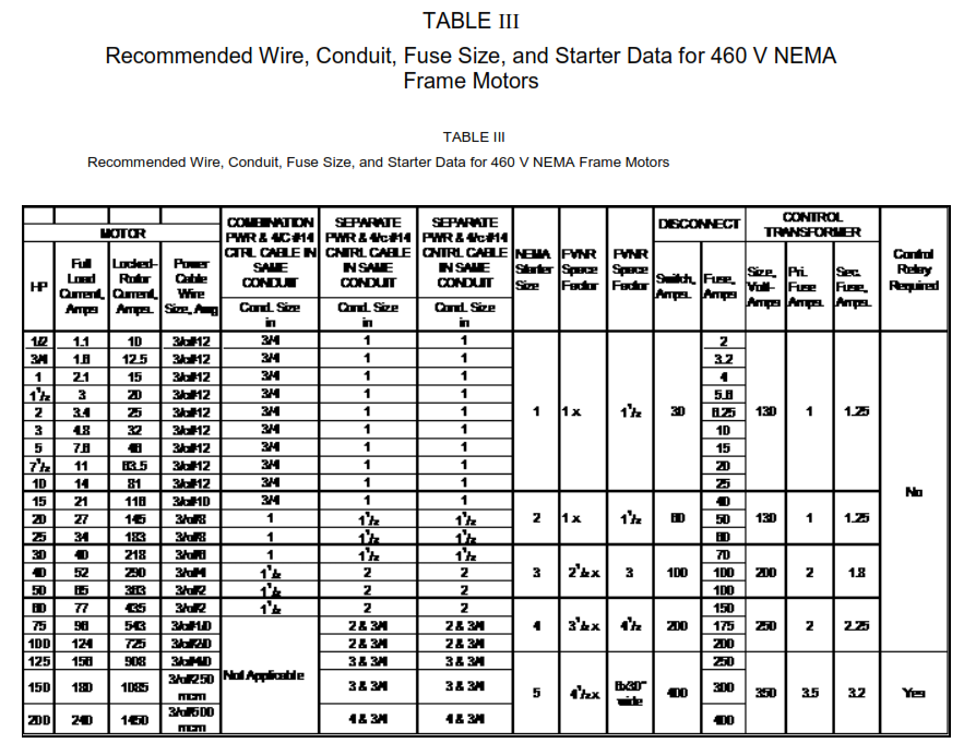
- Cables, conduit, fuse size and starter data shall be in accordance with Table III.
- The manufacturer shall conform to API 540, Section 6, Table 1 and Table 3 for motors to be installed in special conditions.
Main keywords for this article are Induction Motors Design Requirements below 150 kW in Plants, How Induction Motor Starts, Induction Motor Control, Working of Induction Motor, Induction Motor Testing.
Induction Motor Voltages
The most widely used standard nominal systems voltages for motors covered by this article are as shown below. The motor data sheet will show the specific voltage requirement for the required application.
- Standard Nominal Systems Voltages:
120, Single phase, 60 Hz
480, Three phase, 60 Hz - Three phase motors rated 0.4 kW, (0.5 HP) to 150 kW, (200 HP) shall have a nameplate rating of 460 V if connected to a 480 V system.
- Single phase motors rated below 0.4 kW shall have a nameplate rating of 115 V.
Number of Phases
- Motors 0.4 kW, (0.5 HP) to 150 kW (200 HP) shall be three phase.
- Motors below 0.4 kW (0.5 HP) shall be single phase.
Starting Methods
- Motors shall be designed for full voltage starting, and rated for continuous operation unless otherwise stated on the motor data sheets.
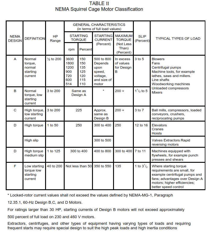
- Motors shall be able to overcome starting load inertia as well as accelerating the load under rated voltage conditions without heat damage. Starting currents shall meet Table II requirements.
- Motors shall be capable of accelerating their driven load when the motor terminal voltage is 80 percent of the rated motor terminal voltage without exceeding rated temperature rise.
- Starting duties from cold start shall be a minimum of three starts in short succession.
- Starting duties from a hot condition where the motor is at a temperature not exceeding its full load operating temperature shall be two starts in quick succession.
Insulation Class
Motors used in an ambient temperature of 50°C shall have class F insulation, but shall still have motor temperature rise to meet NEMA MG-1 requirements for Class B insulation. This is, for motors with a 1.0 service factor, 70°C rise above 50°C when measured by the resistance method.
NEMA Design Letters
Motors are classified based on starting performance, (torque characteristics and locked-rotor currents), with design letters. The NEMA standards set out parameters which are shown in Table II.
Service Factor
- Standard NEMA frame motors generally have a service factor of 1.0 with no margin for exceeding the nameplate rating. Continuous loads in excess of the nameplate rating shall not be imposed as this will greatly reduce the life of the motor insulation.
- Where intermittent operation at higher than the basic motor rating is expected, a service factor of 1.15 shall be specified on data sheet.
- Space Heaters
- Space heaters shall be specified for motors with operation rated above 30 kW (40 HP).
- Unless otherwise indicated on data sheet, space heaters shall be rated for 240 V and operated in 120 V single phase operation.
- Space heater leads shall be terminated in a terminal box separate from the motor terminal box.
- An engraved caution nameplate shall be provided on the front of the motor terminal box. The nameplate shall have yellow background with black engraved lettering in English stating:
CAUTION Space Heaters may be Energized
Insulation System
- Motor insulation systems shall conform to the requirements of ANSI/IEEE 841.
- Form wound motors shall have sealed insulation systems consisting of two complete vacuum/pressure impregnation processes with an epoxy resin-mica compound impervious to moisture. To avoid cracking, the winding end-turns, tightened securely, shall be completely covered and filled with resin to withstand vibration and movement.
- The insulating material shall be resistant to reaction with the lubricating fluid to be used.
Adjustable Frequency Drives
- Where process requirements dictate variable speed operation, squirrel cage induction motors shall be used with variable frequency drives.
- Adjustable frequency drives shall be considered over traditional throttling techniques and conventional methods of speed adjustment in applications where the load torque varies with speed, to minimize maintenance and take advantage of the inherently high efficiency of this kind of equipment.
- Where available, the motor and variable frequency drive shall be specified as a package. If this is not possible, there shall be a documented liaison between the motor and variable frequency drive suppliers as to the application of the equipment.
Grounding
- Motors of 0.4 kW (0.5 HP) and above shall be provided with a ground lug or pad on the motor frame. In addition a ground connection shall be provided in the inside of the terminal box.
Induction Motor Mechanical Design Criteria
The majority of motors covered by this specification will have grease lubricated antifriction bearings.
- Motors shall be fitted with replaceable shaft seals of the non-contacting while rotating type.
- Seals shall be fitted on both the drive and non-drive ends of the shaft.
- Fans shall be non-sparking bronze alloy or conductive plastic and shall be suitable for rotation in either direction.
- Motors weighing more than 25 kg shall be provided with one or more lifting eyebolts, rings, or lugs capable of supporting the weight of the motor.
Construction Enclosure Type
NEMA Motor Enclosure Definitions:
XP- Explosion-Proof for Class 1, Division 1
O- Open
DP -Drip Proof with Screens
TENV -Totally Enclosed Non-ventilated
TEFC -Totally Enclosed Fan Cooled
Terminal Box
- For outdoor motors, diagonally split cast iron terminal boxes shall be provided. The enclosure protection shall be as per NEMA MG-1 requirement.
- Terminal boxes shall be weatherproof, gasketed and oversized with leads between motor housing and the sealed terminal box.
- For indoor motors the terminal box may be the manufacturer’s standard.
- Terminal box location shall be on the right hand side, as seen from the non- drive end of the motor.
- Terminal boxes shall have threaded conduit entrances and shall be rotatable through 360° in 90° steps.
- The motor lead terminal box shall have an internal ground termination connection point.
Bearings and Lubrication
- Motor bearings shall be grease lubricated, antifriction type. Grease fittings shall be located so that the motors may be easily lubricated while in service.
- Antifriction bearings shall have a minimum L-10 life of 40,000 hours when operated continuously at rated speed and load as calculated by the method contained in ANSI/ABMA Standard B9.
- Bearings shall be supplied with rust inhibiting grease compatible with polyureathickened grease.
- Each bearing housing shall be provided with two tapped and plugged openings, one to receive a pressure grease fitting and the other for purging the old grease during regreasing operations. Grease nipple shall include relief devices to prevent overfilling.
- Non-greasable factory lubricated sealed bearings are permitted for fractional kW motors.
Vibration and Balancing
- Motors shall be dynamically balanced. The use of solder or similar deposits for balancing is not acceptable. Parent metal removed to achieve dynamic of static balance shall be removed in a way so as not to affect the structural strength of the rotating element.
- Motors 2, 4, 6 or 8 pole, shall meet the levels of vibration specified in IEEE 841, clause 6.9 and below when tested at no load on elastic mounting, as detailed in NEMA MG-1, Part 7 and when bolted to a heavy, flat base whose natural frequency with motor mounted is removed by at least 25 percent from the motor frequencies referenced below:
a. Motor unfiltered vibration at rated voltage and frequency shall not exceed 2.03 mm/s peak velocity for 2-, 4-, and 6-pole machines, and 1.52 mm/s peak velocity for 8-pole machines, when measured in any direction on the bearing housing and tested uncoupled with 1/2 height key in the shaft extension key way.
b. Motor filtered vibration at rated voltage and frequency shall not exceed 1.27 mm/s peak at frequencies of 2n (twice speed) or 2f (twice frequency).
c. Motor unfiltered axial vibration shall be tested in accordance with ANSI/IEEE 841 and shall not exceed 1.52 mm/s peak on bearing housings. This limit shall not apply to roller bearings.
Noise Requirements
Noise requirements shall not exceed 85 dBA under no-load condition at a distance of 1 meter from any major surface when operating in a reflective or absorbent environment.
Vertical Motors
- Solid shaft vertical motors are preferred for all applications except those in which the connection to the driven equipment is a sectional shaft that may unscrew and lengthen during reversal of rotation.
- Unless otherwise specified, angular contact bearing capable of thrust in both directions shall be required for vertical flange mounted motors with thrust loading. Where the motor shaft is solidly coupled to the driven apparatus, the thrust capacity of the thrust bearing shall be sufficient to carry the weight of the rotating elements of the motor and the external axial thrust loads (in either or both directions), as well as the radial load specified.
- For vertical motors which are designed for external thrust loads, the thrust bearing shall also be rated for a minimum life of 10000 hours continuous service at 100 percent of the maximum (during operation at rated capacity, stopping or starting) specified up and down thrust. Thrust bearings shall be located at the top of the motor.
- 8.4 Externally mounted slinger shall be shrink fitted to the motor shaft above the motor housing or stainless steel rain shield. It shall be rigidly mounted on the frame to prevent water entering the bearing housing.
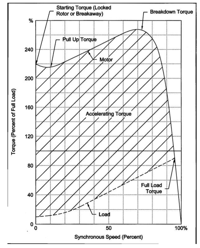
Torque Vs. Speed
- The torque available at the motor shaft shall satisfy that required by the driven equipment during starting. Accelerating and normal operating speed shall be in accordance with Table II.
- For Starting Torque (Locked Rotor Torque), Pull Up Torque, Breakdown Torque, and Full Load Torque for a typical ac induction motor, see Figure 1.
Induction Motor Nameplates
Nameplates shall be engraved and made of stainless steel securely fastened to the motor with stainless steel screws. The nameplates shall have the following minimum information:
(i) Manufacturer’s name
(ii) Motor type and frame designation
(iii) Year of manufacture
(iv) HP/ kW output
(v) Maximum ambient temperature
(vi) Insulation system designation
(vii) RPM at rated load
(viii) Frequency
(ix) Number of phases
(x) Rated load amperes
(xi) Service factor
(xii) Voltage
(xiii) Code letter for locked rotor kVA based on NEC (NFPA 70) Article 430, Table
430-7(b) after conversion from kW to equivalent HP rating
(xiv) Enclosure Type
(xv) Power Factor
(xvi) Serial Numbers
(xvii) Duty Cycle
(xviii) Bearing Number
Induction Motor Testing and Inspection
- Motors shall be inspected and tested in accordance with the applicable NEMA MG-1 and IEEE 112 Standards. Special test requirements shall be listed in E06-X01.
- Checks shall be carried out for dimensions, mounting hole positions, shaft centerline, and details of drive end shaft.
- Each motor shall be tested to demonstrate freedom from mechanical and electrical defects.
- Minimum testing shall include:
(i) Determination of locked-rotor current
(ii) Measurement of no load current
(iii) Measurement of no load speed (iv) Measurement of noise level
(v) High potential test
(vi) Insulation resistance test by megaohm meter
(vii) Measurement of winding resistance
(viii) Observance of motor operation and vibration at no load
(ix) Measurement of 20 percent overspeed - Complete Test. When specified, the following tests shall be carried out in addition to the tests above:
(i) Measurement of polarization index
(ii) Measurement of locked rotor torque
(iii) Full load heat run
(iv) Observance of bearings and mechanical operation of motor at full load, including vibration measurement at final operating temperature
(v) Determination of slip at full load
(vi) Determination of efficiency and power factor at 1/2, 3/4 and full load
(vii) Determination of breakdown torque
Figure 1
Main keywords for this article are Induction Motors Design Requirements below 150 kW in Plants, How Induction Motor Starts, Induction Motor Control, Working of Induction Motor, Induction Motor Testing.
Low Voltage Motor kW Rating and Equivalent HP Rating
NEMA Squirrel Cage Motor Classification
Main keywords for this article are Induction Motors Design Requirements below 150 kW in Plants, How Induction Motor Starts, Induction Motor Control, Working of Induction Motor, Induction Motor Testing.
Recommended Wire, Conduit, Fuse Size, and Starter Data for 460 V NEMA Frame Motors
Main keywords for this article are Induction Motors Design Requirements below 150 kW in Plants, How Induction Motor Starts, Induction Motor Control, Working of Induction Motor, Induction Motor Testing.


