Motor normally shall be used to drive a pump, compressor or other constant speed, continuously operated equipment. All motors shall be designed and provided with protection against chemicals, corrosion and high humidity conditions. Main keywords for this article are SYNCHRONOUS MOTOR ELECTRICAL DESIGN, SYNCHRONOUS MOTOR TESTING, SYNCHRONOUS MOTOR DIAGRAM, SYNCHRONOUS MOTOR SPEED CONTROL, WORKING PRINCIPLE SYNCHRONOUS MOTOR.
References
American National Standards Institute (ANSI)
C50.10 Rotating Electrical Machinery – Synchronous Machines
The noise level limitations shall be in accordance with this article (Click Here). When used for noise control, acoustical absorbent material shall be designed to resist shredding and shall be adequately supported with corrosion resistant fasteners or wire mesh. Complete information including material specification and installation details shall be submitted with the proposal.
The motor shall be capable of withstanding a 20 percent overspeed without mechanical damage.
The manufacture, performance, and testing of synchronous motors shall be in accordance with NEMA MG 1, IEEE 115, and IEEE 429 Standards.
A transient torsional and lateral response analysis shall be performed for the entire mechanical train by the driven equipment manufacturer. All the motor applications shall use pedestal type mounting arrangement (inboard and outboard bearing) except slow speed motors used for reciprocating compressor which may have engine type mounting arrangement (outboard bearing only.)
WORKING PRINCIPLE SYNCHRONOUS MOTOR
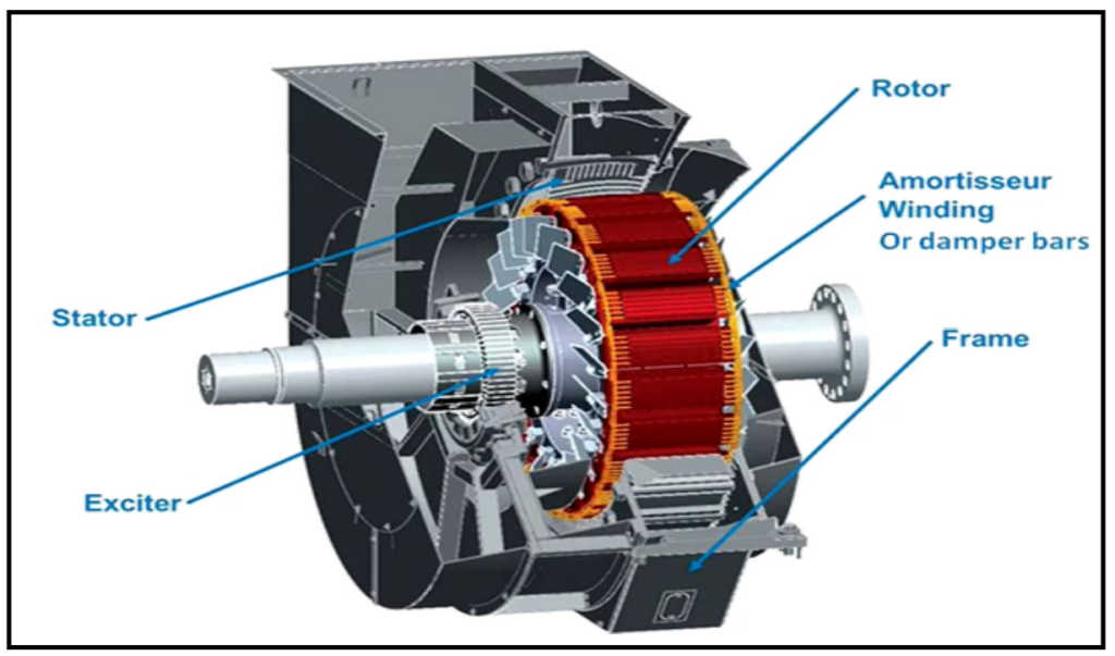
SYNCHRONOUS MOTOR DIAGRAM
Synchronous Motor Electrical Design
Rating and Voltage
All motor ratings shall be based on 1.0 service factor for 50 °C ambient temperature condition. All motor ratings shall be based on a temperature rise of 70 °C (158 °F) measured by resistance at 1.0 service factor.
Stator Windings
- The windings shall be Wye-connection with both ends of each winding brought out to a main terminal box for external connection. Either end of the winds shall be for phase terminals. All leads shall be separated, insulated and braced.
- The motor shall be electrically and mechanically capable of withstanding the forces developed during electrical faults without winding distortion or mechanical failure when operating at rated kilowatts, and 10 percent over voltage. The stator core and windings shall meet the following requirements.
a. The stator core mounting shall be designed to absorb the vibrations caused by the rotating magnetic field.
b. The stator coils shall be form-wound of insulated copper strands bonded to each other. Coil ground wall and turn-to-turn insulation shall be an all mica system, vacuum pressure impregnated with an epoxy resin. For motor rated above 4 kV, the coils shall be coated to suppress corona.
c. All stator windings and connections shall be copper. All rotor windings in general shall be copper and/or copper alloys. d. After all insulation is applied to the coils, each coil shall be individually given a turn-to-turn impulse test. Minimum test voltage shall be the machine terminal voltage and shall have a rise time of 0.1 – 0.2 ms.
e. The stator shall be tested after all coils are installed, wedged into position and temporarily connected. A second test shall be performed when winding of the stator is complete. DC test voltage shall be minimum of 1.7
times service voltage. - The motor Seller shall determine if two-pole motors should be provided with damper windings to reduce the magnitude of oscillating torques that are produced during transient conditions such as system faults and Subsequent voltage recovery. Rotor damper windings may beneficially improve motor performance and stability. Amortisseur windings shall be provided on all motors with four (4) or more poles. The amortisseur windings shall be sized to develop adequate starting and accelerating torques.
Synchronous Motor Starting Capabilities
a. All motors shall be designed for across- the-line starting at full rated voltage. Single motors connected to captive transformers shall be capable of overcoming the inertia of the load on starting as well as accelerating the load to rated speed under both rated and 70 percent of the rated voltage conditions or voltage conditions specified on Data sheet during starting without injurious heating.
b. Motors shall be capable of making the following starts:
Three (3) starts in succession, coasting to rest between starts, with the motor initially at ambient temperature. Two (2) start with the motor initially at its rated temperature. One (1) start every hour after a and b, but not exceeding four (4) starts per 24- hour period. These restart requirements shall apply when the moment of inertia of the load, the load torque during acceleration, the applied voltage, and the method of starting are those of which the motor was designed.
Synchronous Motor Performance
a. When the driven load requires a variable torque during each revolution, the combined installation shall have sufficient inertia in its rotating parts to limit the variations in the synchronous motor armature current to a value not exceeding 66 percent of the full-load current.
b. Pull-out torques shall not be less than 150 percent of the full-load torque for motors operating at 1.0 power factor and 175 percent of the full-load torque for motors operating at 0.8 power factor (leading).
b. The adjustable speed drive motors shall be designed to perform with harmonics generated from static converters/inverters used for adjustable speed drive system. It will be Seller’s responsibility to coordinate with the
supplier of the adjustable speed drive system to obtain all necessary harmonics data and design the motor for the specified operation.
c. The current pulsation shall not exceed 66 percent of rated RMS full load current for all specified conditions of loading. Lower values shall apply when specified on data sheet. The joint effort of the manufacturers of the motor
and of the driven equipment are required when necessary to meet the specified limit.
Synchronous Motor Insulation System
- The motor shall be capable of operating at a 15 percent overload continuously without exceeding the Class F temperature rating of the insulation.
- The motor shall be capable of withstanding, without mechanical injury for 30 seconds, any type of short circuit at its terminals when operating at rated hp, power factor and 10 percent over voltage, provided the maximum phase current does not exceed the maximum phase current obtained from the threephase fault. The motor shall also be capable of withstanding, without injury, the thermal effect of unbalanced faults at the motor terminals for 30 seconds duration or less, provided the integrated product (l2)2 for motor negative phase sequence current (l2) and time (t) does not exceed 30. The criteria for no injury to stator windings is that the windings shall withstand a normal maintenance high-potential test. There shall also be no visible abnormal deformation or damage to the winding coils and connections.
- The motor shall be electrically and mechanically capable of withstanding the forces developed during electrical faults and during a maximum out-of-phase synchronizing application without winding distortion or mechanical failure when operating at rated kilowatts (horsepower), rated power factor and at 110 percent of rated voltage.
- The motor field winding, especially the end turns, shall be protected against shorts and damage caused by the corrosive atmosphere prevalent in a petrochemical plant. The field winding insulation system shall maintain its integrity while withstanding the centrifugal forces and thermal stresses at Class F temperature without damage. Special attention shall be given to ensure adequate support of both coil-to- coil connections and coil-to-main field lead connections.
- Motor field windings shall be pressure heated to consolidate insulation and copper windings into a solid bonded condition. Special care shall be taken in assuring the field ends are properly coated for making them resistant to corrosive attack. Especially, the end turns shall be protected against shorts and damage caused by the corrosive atmosphere prevalent in petrochemical plants.
- Extended solid bus leads used in terminal boxes of large, medium-voltage motors to accommodate connection of the supply conductors, the surge protection equipment, and the metering and relaying transformers shall be fully insulated for the voltage class of motor and firmly supported.
- Motors, with the exception of large, medium-voltage motors having extended solid bus leads, shall be provided with flexible pigtail leads composed of tough silicon rubber insulation (not terminated) in the terminal box for connection to an external supply circuit. The leads shall be fully insulated, provided with permanent identification, and fitted with connection lugs.
Synchronous Motor Sealed Insulation Systems
Stator or Winding
The stator windings shall have vacuum-pressure impregnated with an epoxy resin sealed insulation systems to ensure an impervious seal against moisture and chemicals. Sealed insulation shall be tested in accordance with the specific requirements in NEMA MG-1 and Section 4.3.4.
Exciter Winding
The insulation system for the exciter field and armature windings shall be Class F. Temperature rise during normal operation shall be limited to Class B temperature rise.
Synchronous Motor Excitation Systems
- Each synchronous motor shall be equipped with a brushless excitation system consisting of a three phase alternating current (AC) exciter with revolving armature and stationary field, three-phase bridge rectifier, motor field starting and discharge resistor, and necessary static control modules to provide full function excitation control as described below:
a. Utilize field starting and discharge resistor for limiting the induced voltage across the motor field during starting and pull-out cycles to a value well within the dielectric limitation of the field insulation, and for obtaining maximum torque with minimum line current during starting and pull-in.
b. Ensure positive application of the field if for any reason the motor should synchronize on reluctance torque.
c. Sense the proper speed for synchronizing to ensure pull-in with minimum line disturbance and provide positive application of excitation at the optimum rotor position and phase angle after the proper synchronizing speed had been reached.
d. Remove direct current (DC) power from the field and simultaneously apply the field discharge resistor when pull-out results.
e. Provide automatic application of the field for resynchronizing. - Static control devices shall be of a type and design that can be factory set or calibrated, and that will require no planned onsite adjustment for changes in ambient conditions or repeated use of components.
- The control modules shall be replaceable as complete components requiring no contingent modifications of wiring or circuitry and no on site tuning or adjustment.
- Rotating control modules and devices that are mounted on the shaft and rotor shall be readily accessible through easily removable covers or plates and shall not require extensive disassembly of the motor housing for removal.
- Components such as rectifier diodes, field discharge resistors, thyristors, and control modules, shall be of such characteristics and design as to ensure continued operation and dependability under applicable centrifugal stresses and specified operating conditions outlined in the motor Data Sheet(s) and/or referenced Specifications.
- The motor manufacturer shall specify the rated current and voltage of the exciter field at rated and 115 percent operating conditions. A field voltage of 90-115V DC is preferred.
- The motor manufacturer shall furnish complete information on the functioning of the brushless excitation system along limiting motor parameters. This information shall include the motor damper winding thermal capacity in terms of time-current.
- The motor field for two (2) pole machines shall be provided with a brushless field ground detection system (FGDS), or similar equipment for monitoring the motor field. The FGDS shall have built in time delay to eliminate nuisance alarms.
- The excitation system for two (2) pole machines shall be provided with an exciter diode monitor (EDM) to detect and alarm failure of a power rectifier which either fails open or shorted.
- The exciter shall be sized to provide 25 percent capacity in excess of that required to supply the field excitation of the motor at rated operating conditions.
- The brushless excitation system shall be totally enclosed force-cooled utilizing air ducted from the main motor air stream.
SYNCHRONOUS MOTOR SPEED CONTROL
Main keywords for this article are SYNCHRONOUS MOTOR ELECTRICAL DESIGN, SYNCHRONOUS MOTOR TESTING, SYNCHRONOUS MOTOR DIAGRAM, SYNCHRONOUS MOTOR SPEED CONTROL, WORKING PRINCIPLE SYNCHRONOUS MOTOR.
Synchronous Motor Mechanical Design
Enclosures
- Motor enclosures to suit environmental requirements shall be in accordance with the requirements of the API 546, reference standards and documents.
- All the enclosures bolts, studs and other fastening devices shall be made of AISI 300 Series stainless steel.
- Motors enclosures to suit environmental requirements shall be in accordance with the requirements of the API 546, referenced standards, and documents. Where TEAAC enclosures are specified, the cooling air for the heat exchanger shall be supplied either by a shaft driven fan (preferred method) or by an externally mounted auxiliary blower. For special purpose motors, external auxiliary blowers, if supplied, shall be furnished in a 100 percent redundant, configuration.
- Totally enclosed water-air-cooled (TEWAC) motors shall have a minimum of two (2) water coolers to provide air cooling with in plant cooling water supplied at 35 °C (95 °F) and 440 kPa gauge (65 psig). The coolers shall have capacity to dissipate the heat losses of the motor when it is operated at rated load, voltage and power factor. The coolers shall be sized so that the motor can be operated at 100 percent of capacity while one (1) cooler is out of service. The water cooler design shall be based on a maximum water temperature increase across the coolers of 14.5 °C (26 °F) and a maximum pressure drop of 68 kPa gauge (10 psig). The design cooling water velocity shall be 2 m/s (6.5 f/s), minimum, to 3 m/s (10 f/s), maximum. The water cooler shall be designed to withstand a maximum pressure of 690 kPa gauge (100 psig).
- The coolers shall be arranged so that they are completely filled with water during operation. They shall be the removable bundle type designed and fabricated with flanges and shall be in accordance with TEMA C and ASME Code design criteria with the equivalent documentation. Each cooler shall be protected with an epoxy coating. They shall also permit removal of the waterbox for cleaning of any section when required without shutting down the motor.
- The coolers shall be mounted in the motor housing and arranged so that in case of a leak, water cannot impinge upon the winding. Double-tube coolers shall be provided on all the motors rated above 7500 Kw (10,000 hp).
- Flow-sensing devices with SPDT contacts shall be provided for mounting in the water supply piping of each cooler to sense low and high flow.
- Two (2) 100 ohm, platinum resistance temperature detector (RTDs) elements shall be furnished at the inlet and the outlet of each cooler to measure the input and output air temperatures. The RTDs shall be wired to a terminal strip in a stainless steel NEMA 4X or cast iron junction box.
Frame and Mounting Plates
Epoxy grout will be used for installation of the base plates and sole plates. The vendor shall commercially sandblast in accordance with SSPC SP6, all the grouting surfaces of the mounting plates and shall precoat these surfaces with a catalyzed epoxy primer applied to degreased white metal. The epoxy primer shall be compatible with epoxy grout.
Frame Connections
All conduits shall be rigid galvanized steel. Final terminations to device terminal boxes and devices may be liquid-tight flexible conduits 0.6 m, (24 in) maximum length with approved fittings. All power and control wiring within the confines of the motor shall be heat, moisture, and abrasive-resistant. Within the confines of a baseplate and other areas subject to vibration, stranded conductors shall be used. All wiring shall be stranded copper.
Synchronous Motor Rotating Element
The motor shaft shall be finished throughout its entire length and shall be ground at bearing and sealing surfaces and adjacent to the bearing surfaces, For motors rated over 3700 kW (5000 hp), the shaft shall be provided with an integral shaft hub flange. This flange shall not interfere with the removal of the rotor or other disassembly.
The shaft diameter of the motor shall be designed to eliminate torsional vibration problems. The Seller shall provide a detailed sketch of the major shaft loads and all torsional spring constants for torsional analysis.
The motor shall be designed to provide access for shaft measurement by hand-held probe adjacent to each bearing.
Synchronous Motor Mechanical Assembly
- The rotor shall consist of high grade silicon steel lamination coated to minimize core loss. The coating shall be unaffected by normal temperatures encountered during operation and motor testing. Lamination shall be single piece, rotated to reduce tolerance build-up, punched to fine tolerances, shrinkfitted and tightly compressed to form a permanently clamped and rugged structure.
- The rotor winding, including bars and end rings, shall be copper and/or copper alloys. Cast or fabricated aluminum cage designs are not acceptable.
- Rotors shall be designed to withstand 20 percent overspeed without permanent mechanical deformation.
- Field poles for slow speed machines with a rotor spider design shall be mounted and secured in a manner to prevent undue stresses on mounting bolts which can result in premature failure. Bolt hole diameters in the spider and bolt clearances shall be sized to ensure that the bolts remain properly centered under all conditions of installation and operation.
- When nonmagnetic retainer rings are used, the ring material shall be either 18 Mn – 18 Cr or 18 Mn -13 Cr. Retainer rings made from 18 Mn – 5 Cr material are not acceptable.
- Each field coil shall be tested to ground after installation but before final curing of the rotor. Test voltage shall be at least equal to two (2) times the rated field voltage of the machine.
- Field windings shall be pressure treated to consolidate insulation and copper windings into a solid bonded condition. Special care shall be taken in assuring the field ends are properly coated for making them resistant to corrosive attack.
Dynamics
- Resonances – a. The Seller shall provide a detailed sketch of the major shaft loads and all torsional spring constants for torsional analysis. The sketch shall be supplied no later than six (6) weeks after receipt of Purchase Order.
b. Torsional analysis shall be performed by the manufacturer of the driven equipment. The motor shall not be released for manufacture until the transient torsional analysis of the total train is reviewed. The actual first critical speed of the motors shall be at least 20 percent above the motor no load speed unless specifically approved.
Balancing – The assembled rotor for the motor shall be dynamically balanced in at least three (3) planes at rated operation speed and checked for vibration at 120 percent of operating speed. Final balance shall be performed after painting, baking and with coupling hubs and shaft key. - Balance weights added to the final assembly shall be 300 series stainless steel or an equivalent corrosion-resistant material. Grinding shall not be permitted.
- The rotor fans shall be balanced prior to installation on the rotor. During rotor balancing, correction weights shall be added to the rotor body only and not to the fan blades.
- Motors for special applications, such as those driving high speed compressors, may require motors that are more stringently balanced than specified herein.
Bearing and Bearing Housings
- The bearings for the motor shall be of the standard babbitt-lined, pressure- lubricated, circulating oil-cooled type, designed to prevent the emission of oil or vapor. Upper and lower halves shall be steel-backed, babbitt-lined and bonded to the shell. The front and rear journal bearing shall be interchangeable and shall be designed so that they can be removed without disturbing the rotor. Oil system shall provide lubricating oil to permit an orderly shutdown of the motor in the event of failure of the forced-oil lubricated system.
- Each motor shall be provided with both bearings electrically insulated from the frame and bearing housing. Insulation resistance from the frame shall not be less than one (1) megohm. Warning nameplates reading ‘Insulated Bearing’ shall be mounted on or near all motor bearings that are electrically insulated from the motor frame. Terminal facilities shall be provided to permit direct resistance measurements for testing of the bearing insulation.
- Each bearing shall be furnished with an air pressure seal to prevent oil and oil vapor from reaching the motor internals. Drains for end leakage oil, and proper relieving to prevent oil whirl shall be provided. Labyrinth seals at the shaft entrance shall be provided.
Synchronous Motor Lubrication
- Bearing lube oil shall be supplied from the driven equipment Seller’s lube/seal oil console. The supply pressure at each bearing shall be 140 kPa gauge (20 psig) unless specified otherwise by Seller having total unit responsibility.
- Flow indicators and temperature gauges shall be furnished in the atmospheric oil drain return line from each bearing. Each flow indicator shall be of the bull’seye type, (Jacoby-Tarbox), and shall be installed with its bull’s-eye glass preferably in a vertical plane to facilitate viewing the flow of oil through the particular line.
- When self-lubrication is the Seller’s standard motor design, sleeve bearings shall be lubricated by oil rings supplied from an integral self-cooled oil reservoir. Oil level sight gauges shall be permanently marked, and easily discernible indication of proper oil level shall be provided. Inspection openings for observing the oil rings shall also be provided.
- The Seller shall furnish single-feed and drain-header connections for each oil circuit. Lube oil piping shall be 304 stainless steel per ASTM 392.
Synchronous Motor End Play and Coupling
The Seller shall specify the maximum rotor end float and maximum coupling end float. The motor shaft position, when magnetically centered, and rotor end play limits shall be permanently scribed on the shaft. A permanent reference point shall be indicated on the bearing housing.
Materials
The stator laminations shall be high grade silicone steel, coated so that they are unaffected by normal temperatures encountered during operation and motor testing; segmented, rotated to reduce tolerance build-up; rigidly mounted and tightly compressed to form a permanently clamped and rugged structure.
Nameplates and Rotation Arrows
- A nameplate and rotation arrow are required on the motor and shall be stainless steel (type 304 or 316) or monel attached by pins made of similar material and located for ease of visibility.
- Equipment containing insulating oils, anti-freeze solutions and any other fluids shall be tagged at openings to indicate the nature of the contents, shipping instructions and storage precautions. Openings that require a rust-preventive shall be tagged to indicate that it has been applied. The tag shall also show the name, type and manufacturer of the rust preventive and its solvent.
- Shaft seals of the motors installed in classified locations shall be constructed so that a purge gas can be introduced.
Synchronous Motor Accessories
Terminal Boxes
- The terminal boxes shall be extra large and sized for the allowable bending radius and stiffness of the motor supply cables for terminating a grounding conductor, to accommodate preformed stress cones, surge protection and current transformers. Oversizing of boxes shall be necessary to accommodate cable sizes larger than normal due to cable derating and voltage drop requirements. The Seller shall be responsible for ensuring that the main motor terminal box is supported at grade level or on the baseplate. All the internal connections shall be insulated and taped for the voltage class. The terminal box shall be rated NEMA 4, heavy gauge steel with a minimum thickness of 5 mm (3/16 in).
- Terminal blocks shall be provided for all low voltage and control wiring. Terminal blocks shall be a noncorrosive type with nickel-plated copper, current carrying components. The spare capacity shall be at least 10 percent of the terminal blocks on any strip. All control and low voltage wiring terminal boxes shall be located on the side of the motor enclosure and shall be either metallic (stainless steel) NEMA 4X or cast iron. The boxes shall be rotatable to allow for connection from any one (1) of four (4) directions at 9??? intervals. A motor lead seal and separator, neoprene gasket shall be provided between the motor frame and the terminal box. Cast terminal boxes shall be provided with threaded conduit hubs or entrances. A minimum of two (2) conduit hubs shall be provided in all control wiring terminal boxes. Fabricated terminal boxes shall be provided with removable plate on bottom for field drilling.
- A tinned-copper grounding bus bar shall be provided in the main terminal box for terminating cable shields and any grounding conductors routed with the phase conductors.
- As a minimum the main terminal box shall be supplied with items a, b, e, g, and k and auxiliary terminal boxes shall be provided with items c, d and g.
- When differential current transformers are provided, secondary leads shall be required and shall meet the requirements of this paragraph.
Winding Temperature Detectors
- Motors rated 750 kW (1000 hp) and above shall have the stator windings equipped with 12, 100-ohm, platinum RTD’s, four (4) per phase, wired to a terminal strip in a metallic, (stainless steel), NEMA 4X or cast iron terminal box for continuation wiring. The RTDs shall be 3-wire and shall be located in each phase where the maximum temperature may be detected. Six (6) of the RTDs shall be used for local temperature indication and six (6) RTDs shall be used for protective relaying. The motors rated below 750 kW (1000 hp) shall be furnished with RTD’s in their windings, as noted in the above paragraph, to provide an accurate temperature monitoring and alarm system in special applications.
- When specified on the motor Data Sheet(s), Rotor Temperature Monitor (RTM) system shall be provided to protect the motor rotor by transmitting temperature information from the rotor to a remote stationary temperature indicator, equipped with alarm and shutdown contacts. The system shall be capable of detecting the temperature of cage bars, cage end rings and rotor field windings. The Rotor Temperature Monitor system shall provide a direct means of determining rotor temperature and utilizing it to protect the rotor from over-heating. The output contacts of the RTM shall be wired into the motor starting circuit to permit motor starting if the rotor temperature is within an acceptable range. A readout meter with adjustable high and low setpoints shall be provided for remote mounting in control panel or switchgear to operate alarm or shutdown contacts when limits are exceeded. Transmitter power shall be derived by means of a stationary power oscillator, operating at a higher frequency relative to the temperature information, a rotary transformer and an AC to DC converter. The scale of the readout meter shall be in degrees Celsius (°C).
- Rotor Temperature Monitor shall have the following features:
a. Actuation of alarm and permissive condition in starting circuits shall be provided which protects against repetitive starts before the rotor has cooled sufficiently.
b. Multiple sensors shall be provided on each rotor to ensure future availability of a usable sensor.
c. The Monitor shall indicate if the thermocouple circuit should become open, or if there is a loss of transmitter signal.
d. The Monitor calibration shall be from the front of the receiver with no adjustments required at the transmitter.
e. The Monitor system shall operate in an ambient temperature range of 40 °C to 50 °C.
Bearing Temperature Detectors
For motors rated 1500 kW (2000 hp) and above, the lower section of each bearing shall be provided with two (2), 100-ohm, platinum RTDs. The RTDs shall be located within 6 mm (¼ in) of the bearing surface. The RTDs shall be wired to a separate terminal box.
Space Heaters
The space heater sheath shall not exceed a maximum temperature of 180 °C or 80 percent of the ignition temperature of specified gas/vapor in hazardous locations for any value at or below the maximum rated ambient temperature of 50 °C and 120 percent of rated voltage. The space heater leads shall be terminated in a separate terminal box from that containing the motor phase leads.
Screens and Filters
Filters shall be capable of filtering airborne particles of 0.0015 mm diameter in size. The air filters shall be securely fastened in place and easily removable for cleaning during motor operation. The filters shall be provided with an explosion proof differential pressure switch with dual NO/NC contacts for alarm and a differential pressure gauge mounted at eye level.
Ground Connections
The Seller shall provide grounding pads for connections to United’s ground grid using 70 mm 2 copper-stranded conductors. Two (2) diagonally opposite ground pads shall be furnished on the motor frame. Where separate pedestal bearings are supplied, each unit shall be provided with a tapped hole in the frame foot for a ground connection.
Vibration Detectors
Each bearing for the motors rated 1500 kW (2000 hp) and above shall be provided with two (2) vibration probes and oscillator demodulators. The probes shall be displaced 90 degrees apart and 45 degrees from the vertical at each bearing. The oscillator demodulator shall be mounted in a separate terminal box with a removable probe holder. Each holder shall be shouldered so that the probe location is maintained when the probe is removed and reinstalled. The holder shall be mechanically locked to the bearing housing and the probe shall be mechanically located in the holder to prevent loosening in service.
Synchronous Motor Testing
- As a minimum, the test listed in API 546 and the following tests shall be performed.
a. Resistance of stator and field windings (cold and hot)
b. Shaft current and bearing insulation
c. Phase sequence
d. Overspeed Operation (120 percent of rated speed)
e. Four (4) hour run test
f. Stator core test
g. Measurement of air gap
h. Measurement of no-load speed
i. Measurement of no-load current for each phase
j. Stator winding immersion test
k. Noise test (8 points)
l. Short-circuited turns on rotor
m. Polarity test for poles
n. High potential test on stator
a. Open circuit and short circuit saturation
b. Efficiency and power factor determination at 50, 75, 100 and 115 percent load
c. Segregated losses
d. Temperature rise (method 4)
e. Speed-torque
f. Pull-out Torque
g. Determination of machine reactances and time constants
h. Locked rotor current
i. Elevated temperature with restricted cooling vibration test
j. Load excitation (Potier reactance)
- During the running tests, electrical and mechanical operation of all equipment shall function satisfactorily. Bearing oil and cooling water pressure and temperature levels of both feed and drains shall be agreed upon prior to the test. The test readings shall not start until all such parameters are stabilized to within plus or minus 3 °C (5 °F). Oil and cooling water pressures, flow rate and temperatures shall be monitored and recorded.
- The motor shall be run at 100 percent and 120 percent of normal operating speed. After the unit has stabilized at these conditions, readings shall be recorded for vibration, oil pressure, and temperature for each operating condition. The job vibration probes, when provided, shall be installed for the test and used to determine the vibration levels.
- Vibration readings shall be monitored and recorded and shall be taken on the shaft at both the nondrive and coupling ends; readings taken on the bearing housings are unacceptable. Vibration amplitude against speed during the coast down from 120 percent of rated speed to rest shall be recorded.
- During the shop test of the assembled motor operating at the no-load speed, the peak-to-peak amplitude of the vibration unfiltered in any plane measured on the shaft, using the job Bentley Nevada proximitor probes adjacent and relative to each radial bearing, shall not exceed the limits listed below including mechanical runout plus electrical runout. If the Seller can demonstrate that electrical runout due to shaft material anomalies is present, the electrical runout shall not exceed 0.25 mil (maximum). Electrical runout can be deduced using acceptable methods by slow-rolling the rotor with a proximity probe.
- The unfiltered vibration level (peak-to-peak) of the assembled motor operating at the 120 percent of rated speed shall not exceed the above value plus 0.5 mil. The amplitude of any discrete nonsynchronous vibration shall not exceed 25 percent of the allowable vibration .
- Stator core test shall be performed on all the motors.
- The voltage surge withstand capability of the stator turn to turn insulation shall be within the envelope defined in Figure 1 of IEEE Standard 522. Two (2) additional stator coils shall be manufactured for all the motors at the same time as the complete stator winding and shall be tested.
- The test of the turn insulation shall consist of successive applications within one (1) minute interval of voltage impulses with a rise time of 0.1 – 0.2 microseconds, applied between the coil terminations. The crest value of the voltage impulse shall be gradually increased until the point of insulation failure is reached. The test voltage shall include values of 2.0, 3.5 and 5.0 pu.
Main keywords for this article are SYNCHRONOUS MOTOR ELECTRICAL DESIGN, SYNCHRONOUS MOTOR TESTING, SYNCHRONOUS MOTOR DIAGRAM, SYNCHRONOUS MOTOR SPEED CONTROL, WORKING PRINCIPLE SYNCHRONOUS MOTOR.