Introduction of Industrial Instrumentation
Industrial Instrumentation
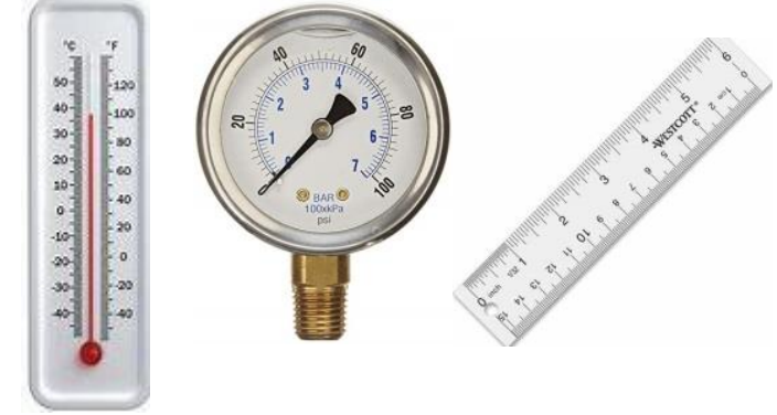
(1) Industrial Instrumentation means to Measure a physical quantity (Process Variable “PV”) & Control through final control devices (Control Valves) to run the plant in safe condition for better production. Instruments may be very simple like:
Glass thermometer to measure heat or cold,
Gauge to measure pressure or temperature etc.
Ruler to measure distance, length or level.
Measuring Systems
There are many industrial measuring systems available in the world. Measurement
means to calculate & convert the physical quantities in to readings and readings have some units. These are called industrial international systems of measurements.
(1) Imperial System is a British System. (FPS System means Foot, Pound & Second).
(2) Metric System is a universal measuring system. (Also called MKS System.) There are many measuring units are available in this system. Like: Meter for Length, Kilogram for Weight, Second for Time, Kelvin for Absolute Temperature, Ampere, Volt & Watt for Electrical, MOL for Substance / Phenomena & Candela for Intensity of Light…etc.
** Most commonly used system in the world is “MKS” means Meter, Kilogram &
Second. Physical Quantities used in Industries: (Also called Process Variables “PV”)
Followings are the most commonly used physical quantities (Process variables) in industrial
instrumentations
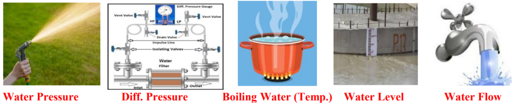
- Pressure and differential pressure
- Temperature
- Level
- Flow
Measurement
Measurement is a process to get reading on an instrument as shown these Steps.
Any instrument which completes below 5 steps is called Gauge.
1st step – Physical quantity——————————- (Process Variable “PV”)
2nd step – Sensing element —————————— (Effect on sensor)
3rd step – Motion assembly —————————— (Movement assembly)
4th step – Pointer movement on a scale —————- (Needle movement)
5th step- Display reading on graduated scale———- (Showing reading)
Measuring process by Gauge

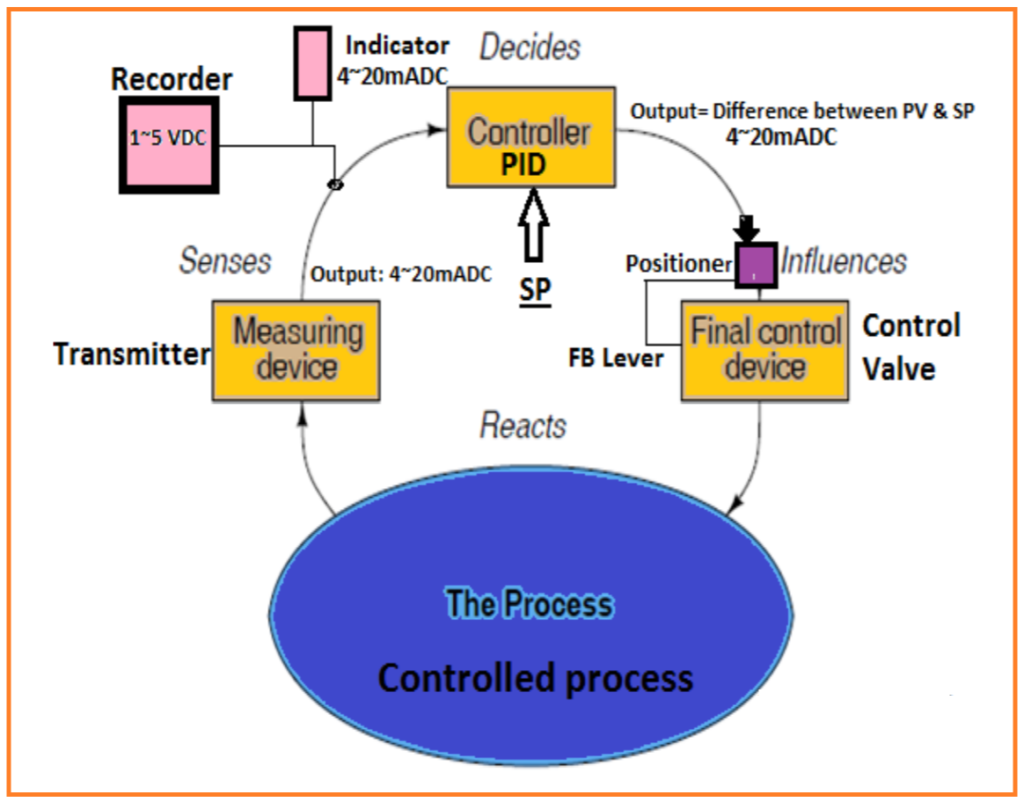
Controller & Final Control Devices
Controller is a device which senses the Difference In between Process Variable (PV)
(Signal received from transmitter) & Set Point then send signal to Control Valve to maintain the PV in limited value.
Theme of automatic controller:
Final Control Devices:
ON-OFF Valve
Shut-Off valve
(OPEN – CLOSE)
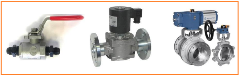
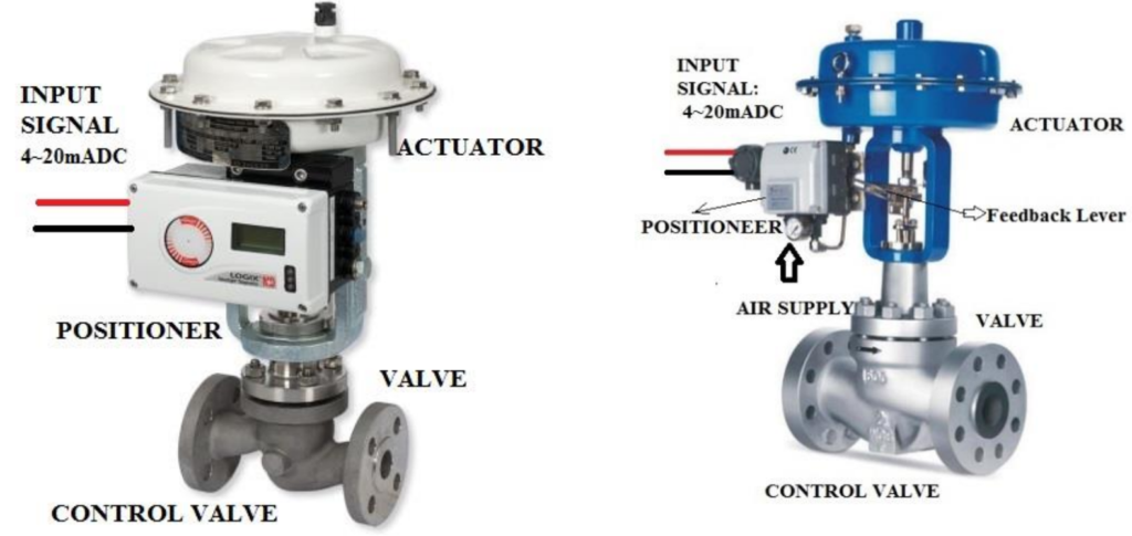
Control valves with positioners:
Categories of Industrial Instrumentation
Industrial Instrument Categories
| Field Measuring Instruments | Controlling system |
| (a) All type of Gauges & Sensors | (a) All types of Controllers & Controlling Modules |
| (b) All type of Transmitters & Sensors | (b) All types of Actuators & Control Valves |
| (c) All types of Detectors & Transducers |
(c) All types of accessories related to Controlling systems |
| Supervisory System | Annunciation System |
| (a) All types of Mimics & Indicating Light units |
(a) All types of Annunciation cards. |
| (b) All types of Recorders, & Data Recording System. Including DCS |
(b) All types of Switches related to Annunciators |
| (c) All types of Analog modules / DCS Analog I/O Cards |
(c) All types of Auxiliary Relays & Timers. |
| (d) All types of Indicators |
Protections (Interlocks & Logics)
(a) Protection of pump Motors, Turbines, Generators, Boilers, Generator & Unit Transformers & All Auxiliaries
(b) Interlock and logic Drawings.
(c) Digital I/O cards.
Commonly Used Items Switch, Relay, Transmitter & Use of 4~20mADC & Signals
Before we start to understand physical quantities (Process Variables), we
should understand basic information of the commonly used items.
1- Switch
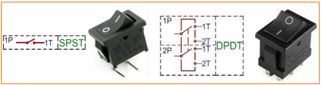
Switch is a device which makes and breaks the electrical contact or ON-OFF contacts. These contacts can be Normal Open (NO) or Normal Close (NC).
2 Position switch (ON – OFF) using two wires is called SPST (Single Poll / Single
Through) switch. Means 1-Input & 1-Output.
4 Position Switch. There is DPDT (Double Pole / Double Through) switch having 2-Inputs & 2- Output as shown below.
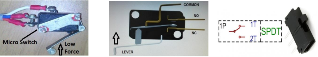
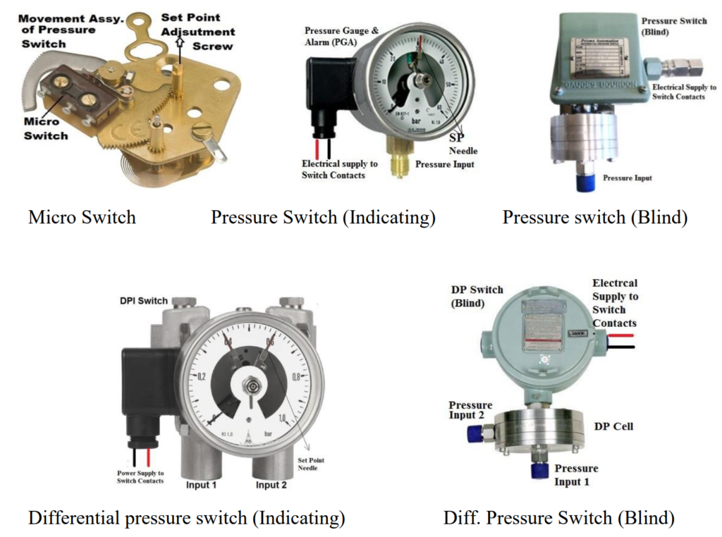
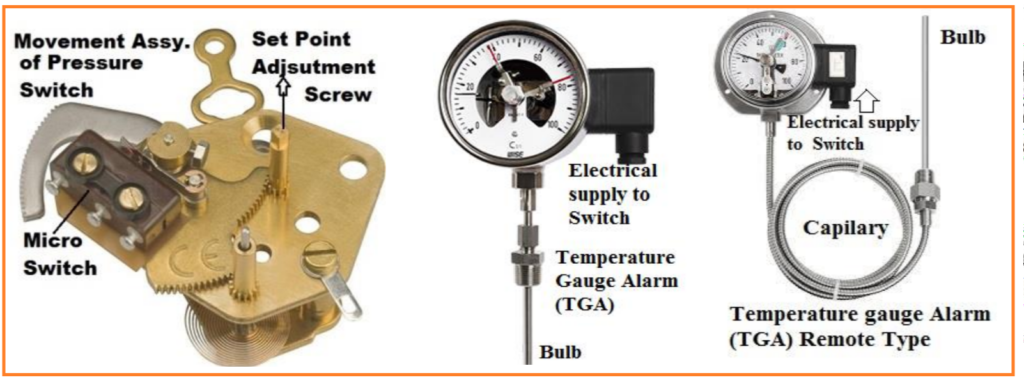
Micro Switch:
Micro switch is an electrical low force operating switch.
- 3 Position switch (NO – NC & COMMON). Using 3 wires called SPDT. (Single Pole / Double Through) Means 1-Input & 2-Outputs. As shown below.
2- Relay
Relay is a device, operating by electrical power supply through one contact to energize coil and provides many types of output contacts (COM. NO, NC = SPDT). Relay can be operated by electrical supply either AC or DC.

Use of Different Contacts in Instrument Drawings:
When we use SPST / SPDT / DPDT switches in Interlocks drawings, we could not
understand that used contacts are closed or open. So some companies used below terms to understand contact conditions used in drawings in rest postion.
a, b & c Contacts

Form “a” contact
“a” Contacts (“Make contacts”) Means contacts are open, required to make it. So “a”
contacts are normally open contacts. This position is in rest condition
without external force. To make a contacts need external force. It can be push,
energizing magnet or energizing relay. This type of contact is SPST contacts.
Form “b” contacts
“b” contacts (“Break contacts”) Means contacts are closed required to open it. So “b” contacts are normally closed contacts. This position is in rest condition
without external force. To break the contacts, external force is required. Its operation is logically inverted from Form A. External force can be push, energizing magnet or
energizing relay. This type of contact is SPST contacts.
Form “c” contacts
“c” Contacts (“Change” or “transfer” contacts) are composed of a normally closed
contact pair and a normally open contact pair that are operated by the same device;
there is a common electrical connection between a contact of each pair that results in only three connection terminals. These terminals are usually labeled as normally
open, common, and normally closed (NO-C-NC). This type of contact is SPDT contacts.
3- REED Switch
A reed switch consists of two or three springy Ferro-magnetic plates called reeds plated, long-life contacts at the tips and capsulated in a sealed glass tube. The two reed type has normally open (NO) contacts, which close (NC) when permanent magnet comes near it. This is called SPST Reed Switch.
A three-reed type is a changeover switch. It has a pair of normally Open (NO) and a pair of normally Closed (NC) contacts & Common terminal (C) contact. Reed switches are actuated by an external permanent magnet field or electromagnet field placed in close position.

Requirement of a Transmitter
Any gauge is showing reading in local area. We need an instrument which can transmit process variable (PV) values to the control room, where we can record and control all above process variables. That’s why we need an instrument which can transmit (PV values) from field to control room. This instrument is called transmitter.
Transmitter: (Steps of Transmitter)
Transmitter is a device which senses the process variable through sensor.
Sensor transfers his effects to motion assembly.
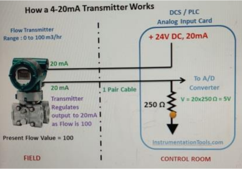
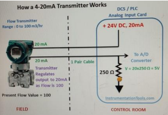
These motions convert into electrical current 4~20mADC with the help of electrical
power supply and transmit this 4~20mADC to Indicator or Recorder or controller.
Then 4~20mADC converts in PV readings and record these values in a recorder. As shown below.
Measuring process by a Transmitter:

All types of transmitters transmit 4~20mADC to the control room to record and
control the process variable (PV) through the controllers and control valves.

What is Process Variable?
PV means signal at real time or present time. It changes in each second. and any signal in past time is called history.
Commonly used Signals in Industrial Instrumentation
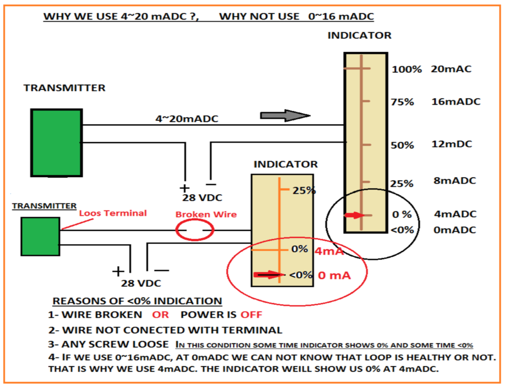
1- Signals from Field Instruments to Control Room
a) 4~20mADC, Current signal from All Transmitters to control room. (Like: Pressure, Differential pressure, Flow, Level, Analyzers Transmitters, Valve position Transmitter & Temperature Transmitter if installed in field.
b) Milli Volt (mV) & 1~5 V DC: from all types of Thermocouples to mV / V/I Converter.
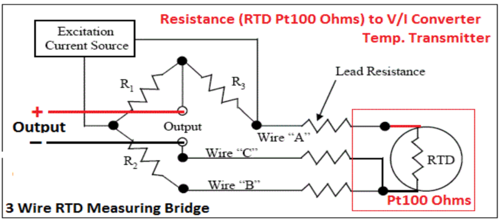
c) Resistance Transducers (ῼ): From Resistance Temperature Detector (RTD Pt100 ῼ at 0C) to Volt Converter (RTD / V/I).
d) ON / OFF or Binary Nos. / Digital Signal (0-1): Contacts / Digital Signals
from All types of Switches to DCS Digital Input Cards / Relays. (Like: Pressure, Differential pressure, Flow, Level, Temperature & Limit Switches
installed in field)
e) 1~5 VDC: 250 ῼ Resistance is used to convert 4~20mADC in to 1~5 VDC by using Ohms Law. V= I x R (Where I = 4~20mADC and R = 250 Ohms)
2- From Control Room to Field Instruments
f) 4~20mADC, Current Signal from All PI & PID Controllers to all I/P
Converters or SMART positioners to operate the control valves.
g) 0.2 ~ 1.0 Bar / 3~15PSI Pneumatic Signal from I/P converter / in SMART
Positioner to operate the control valves.
h) ON / OFF or Binary Nos. / Digital Signal (0-1): Contacts / Digital Signals from DCS Digital Output Cards / Relays allow control power supply to the Solenoid Valves installed on Shut-Off Valves & Control Valves.
i) 110 VDC / (24VDC Used in DCS): Control Power Supply to All Solenoid valves installed on Shut-Off valve & Control Valves.
Pressure & Differential Pressure
Pressure: Pressure is the amount of force applied over the specific size of the area. (Per unit area). To understand (Force “F”), P=F/A
let’s understand the followings
Mass: Every Substance / Element / Object / Material on the earth is Mass. Every
mass has density.
So Mass = Object X Density
Weight: Weight is the Gravitational force in between the Mass (Object) and the Earth. Object has more weight if it has more mass.
So Weight = Mass X Gravity
So Weight = Object X Density X Gravity
(This Weight is called Force)
Now we know the Definition of Pressure.
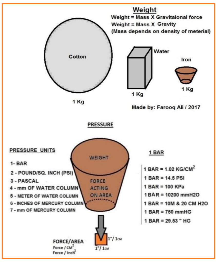
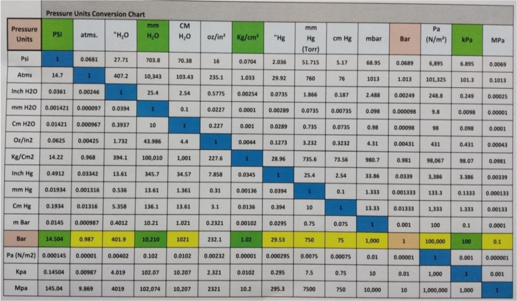
Units of Pressure are as follows
(1) PSI (2) Bar (3) mmH2O (4) Pascal.
Pressure conversion chart in different pressure units
Different Types of Pressure Measurement
There are 4 types of pressure measurement
Atmospheric pressure: The Mass of air has weight and this weight is pressing downward to earth causing atmospheric pressure. So air pressure acting on the earth at sea level is called atmospheric pressure.
Gauge Pressure: Pressure above the atmospheric pressure is called gauge pressure.

3- Absolute Pressure: Atmospheric pressure + Gauge pressure is called absolute pressure.
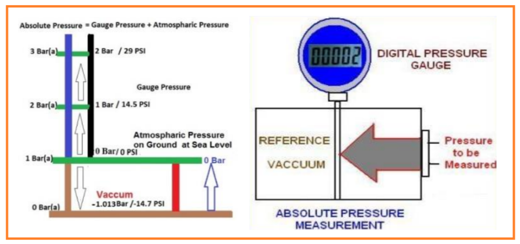
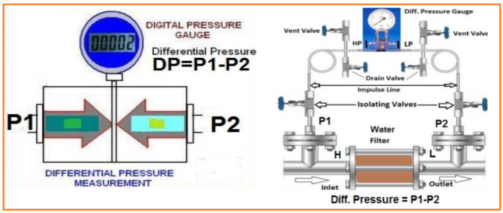
Differential Pressure: The difference between any two measured pressures is called differential pressure.
Example:
Two pressures act on the wall of the car tyre,
1- The pressure of the atmosphere on the outside of the tyre.
2- The pressure we read on the gauge when air is pumped into tyre.
3- Due to the difference of 2 pressures, car tyre lifts up.

Pressure Gauges & Sensors
Pressure Gauge
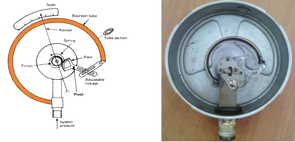
It is a device which takes process pressure through the input port and expands the sensing element and transfer expanding movement through the movement assembly to the pointer which moves on scale of the gauge. This measuring device is called Pressure Gauge.
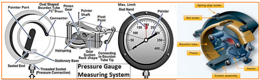
Pressure Gauge and Parts Names:

SENSORS OF PRESSURE & DIFF. PRESSURE
There are many types of pressure sensing elements.
C – Bourdon
The working principle of a “C” bourdon tube
- Outer diameter of “C” bourdon is bigger than the inner diameter of “C” bourdon. Due to the oval shape of “C” bourdon, the area of outer side is bigger than the inner side. So “C” bourdon tries to become in round shape and expands upper side. So movement takes place. Working principle is called (Force & Balance Principle)
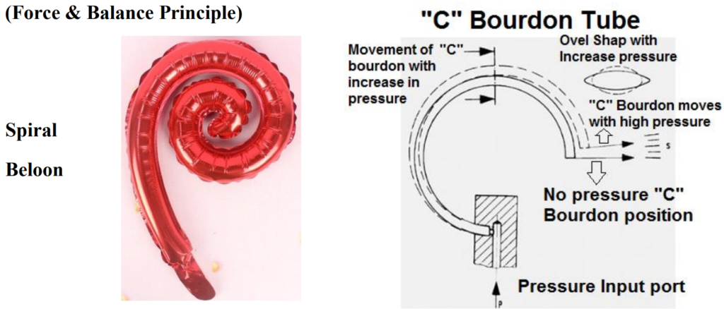
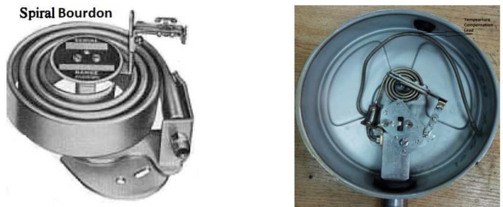
Spiral bourdon:
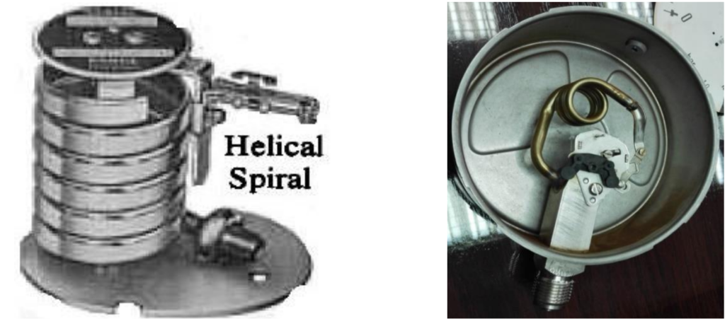
Helical spiral bourdon
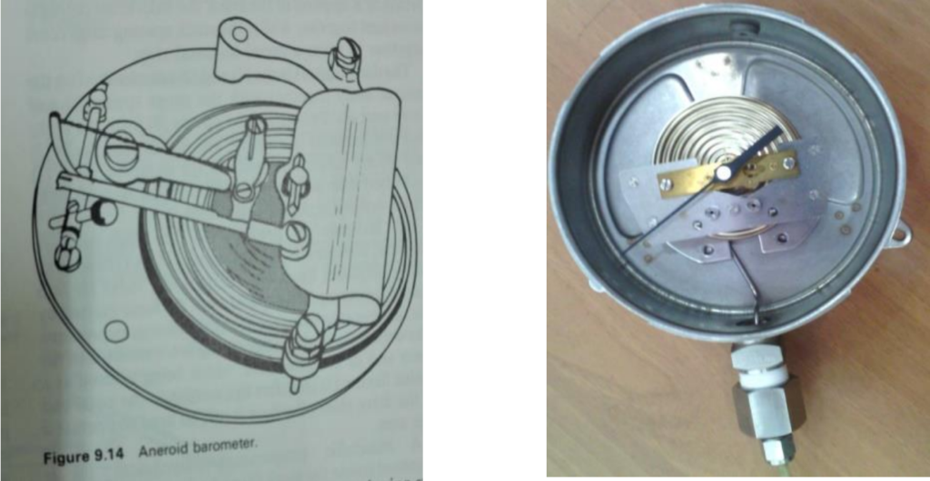
Diaphragm (Used for very Low pressure in mmH2O water column)
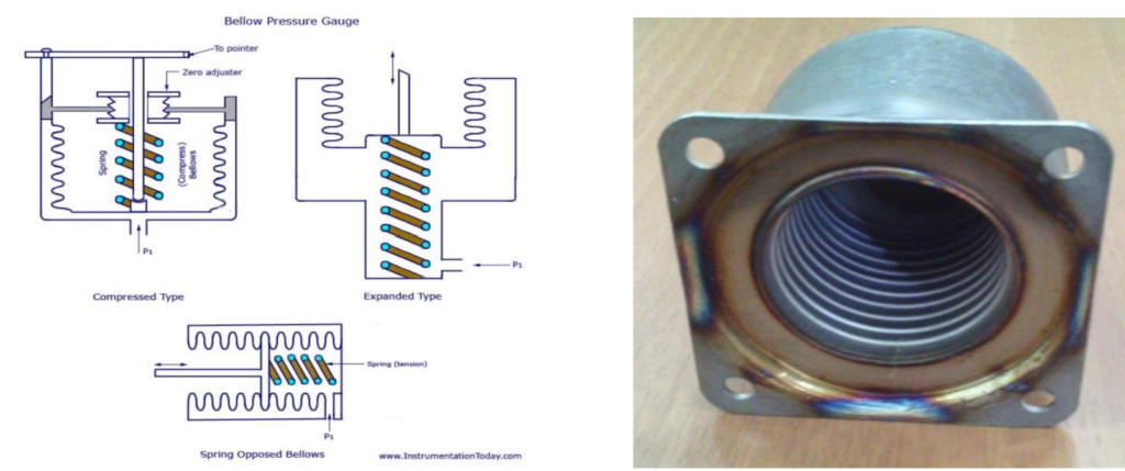
Bellow
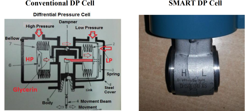
Differential Pressure Cell (Diff. Pressure = P1-P2), P1= High & P2 = Low
Pressure / Diff. Pressure Switch
If we use a Micro Switch in the pressure / Diff. Pressure Gauge, can adjust the Set Point and get ON – OFF contacts at required set point value is called Pressure / Diff. Pressure Switch.
ON-OFF contact can be used for ALARM in control room or START /STOP Pump Motor.
There ae two types of pressure & differential pressure witches (1) Indicating type (2) blind type.
Pressure / Diff. Pressure Transmitter
Pressure & diff. pressure transmitter is a device, which detects pressure or differential pressure, and regulate the analog output current in to 4~20mADC or regulate Digital output according to the input Process Variable (PV) and transfer to the control room.
We can record process values and control the all process variable with help of controllers. We have 2 types of pressure transmitters.
A- Analog Pressure Transmitters. Output: 4~20mADC
B- SMART Pressure & Diff. Pressure Transmitters

1- Analog Transmitter:
This type of transmitters is blind and duff. Even doesn’t know his Tag No. Only have sense to detect effects of PV to Pressure or Diff. Pressure Sensor.
Working principle Force Balance principle. This type of transmitters only produces current (4~20 mADC) and transmit from field to control room.
Draw Back: Analog transmitter cannot remember anything when removed from the field because he doesn’t have memory.
Draw Back: Analog transmitter cannot remember anything when removed from the field because he doesn’t have memory.
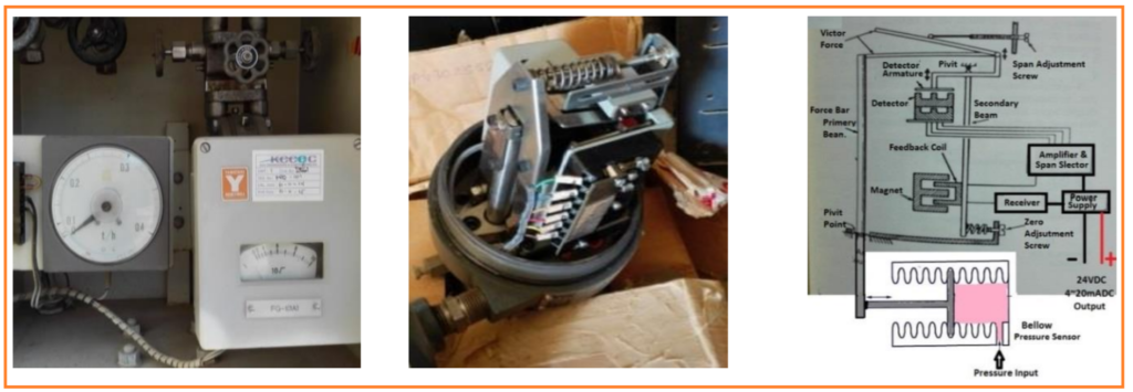
Analog Transmitter Function Block

(A) Formula to convert current in to Voltage is called Ohms Law:
I= V/R or V= I X R (I= mA, R= Ohms)
2- S.M.A.R.T Transmitter: means
Single, Modular, Auto-ranging, Remote, & Transducer
& S.M.A.R.T. (Self-Monitoring, Analysis, And Reporting Technology; written as SMART)
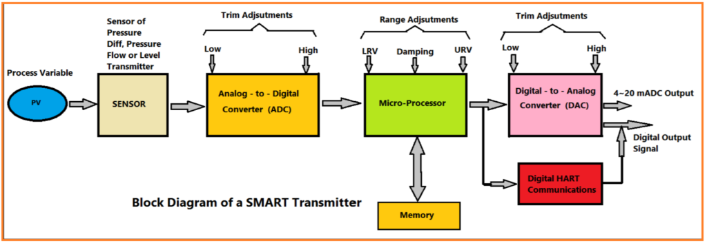
SMART Transmitter
SMART It is a universal type Transmitters having many functions.
1- SMART Transmitter has processor and memory.
2- He can remember everything what we feed any data.
3- He can communicate with communicator from long distance.
4- We can configure his Tag No. Process Name, all data to be measured and Unit to
be Calibrate according to required Range.
5- It has Memory unit we can recall history of transmitter.
6- We can communicate & Calibrate (Low & High Range) / Trim (LRV & HRV) in different units and ranges through communicator.
7- We can configure calibration and maintenance schedule in its memory.
8- It can communicate through communicator in different protocol i.e. HART, PROFIBUS & BRAIN. These transmitters can be used with any network and DCS systems.
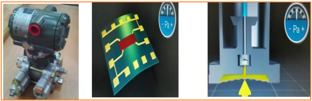
SMART Transmitter Sensors Working Principle:
DP HARP (Differential Pressure High Accuracy Resonant Pressure).
Piezo-Resistance: The Piezo-Resistive effect is a change in the Electrical Resistivity of a semiconductor or metal.
SMART Transmitter Function block
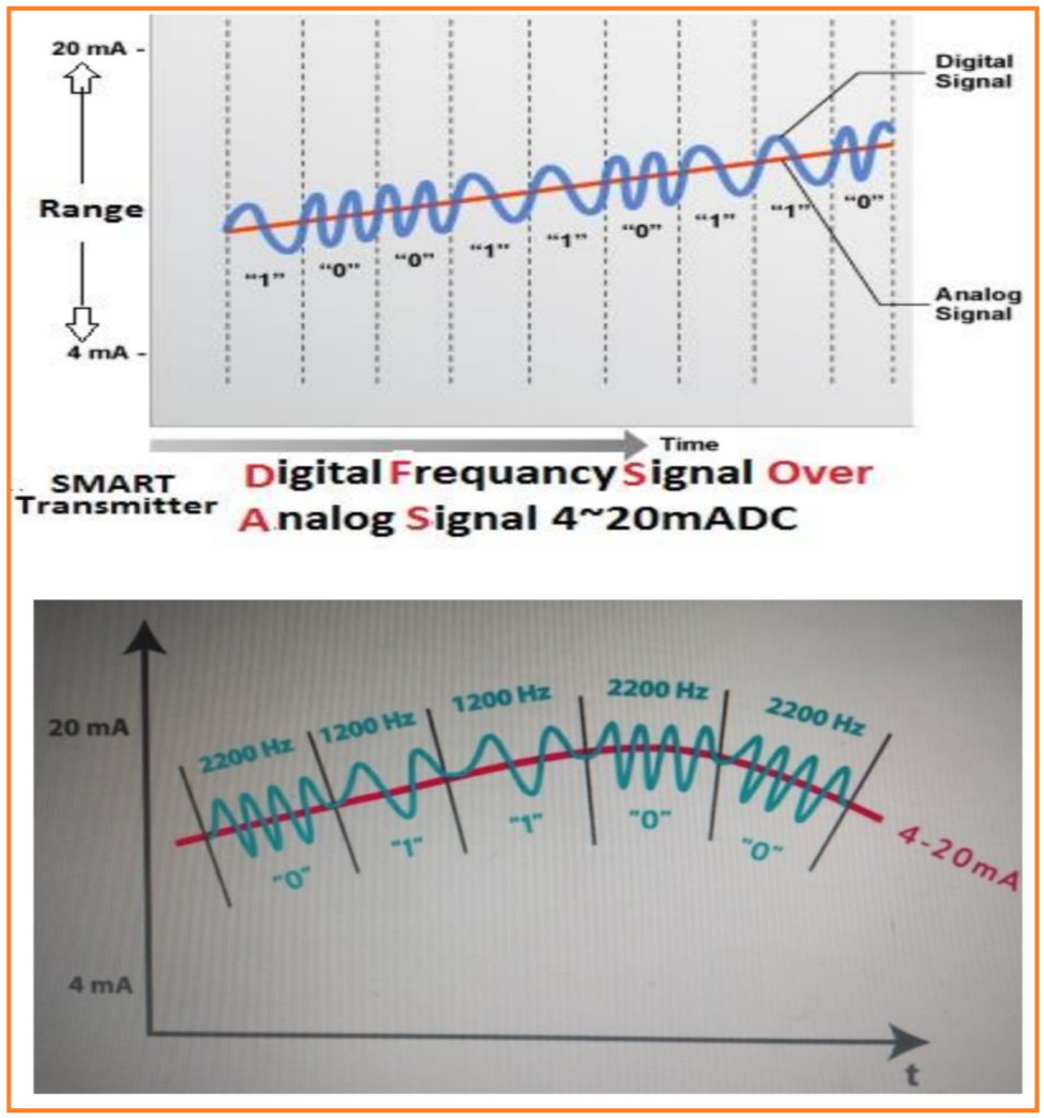
HART Protocol
Highway Addressable Remote Transducer
HART is the working protocol of HART instruments
HART Transmitter has 2 out puts.
1- Analog Current output (4~20 mADC)
2- Frequency output as communication signal (0 / 1)
TEMPERATURE
A temperature means Hot or Cold energy, means thermal energy in any object. It is measured by a thermometer. Temperature is a physical quantity / conditions expressing hot and cold.
Temperature means intensity of heat present in any abject.
Means any object is how much hot or cold.
Temperature is calibrated in one or more temperature scales.
Temperature Units:
The Celsius (oC) scale is known as a Universal System Unit. It is used in most
countries.
Water freezing point is “0” degree Celsius (oC) and boiling point is “100” degree
Celsius (oC).
The Fahrenheit also commonly used in many countries.
The freezing point of water is at “32” degrees (F) and the boiling point are at “212”
degrees (F) as shown below thermometer.
The Kelvin scale is designed to go to Absolute Zero. Means absolute fozen. The
freezing point of kelvin is “273” degree “C” and boiling point is “373” degree “C”.
This unit is not used in industries instrumentation.
“0 Kelvin” means stop motion of electrons and molecules in an atom.
Glass Thermometer
Thermometer: It directly measures the temperature of
any process. Thermometer is made by glass and graduated in
Degree C or Degree F.
Thermometer can be filed by mercury or any liquid which
proportionally expand with heat.
Standard FORMULA of Temperature Convertion.
C/100=F-32/180
Driven Formulas from Standard Formula.
C = (5/9) ( − 32)
F = [(9/5) ] + 32

Temperature Measuring Sensors
There are 4 types of sensors of temperature.
1. Thermometer (As shown in above page) 2. Bulb (Used in Temperature Gauges) 3. Thermocouple (T/C) 4. Resistance Temperature Detector (RTD)
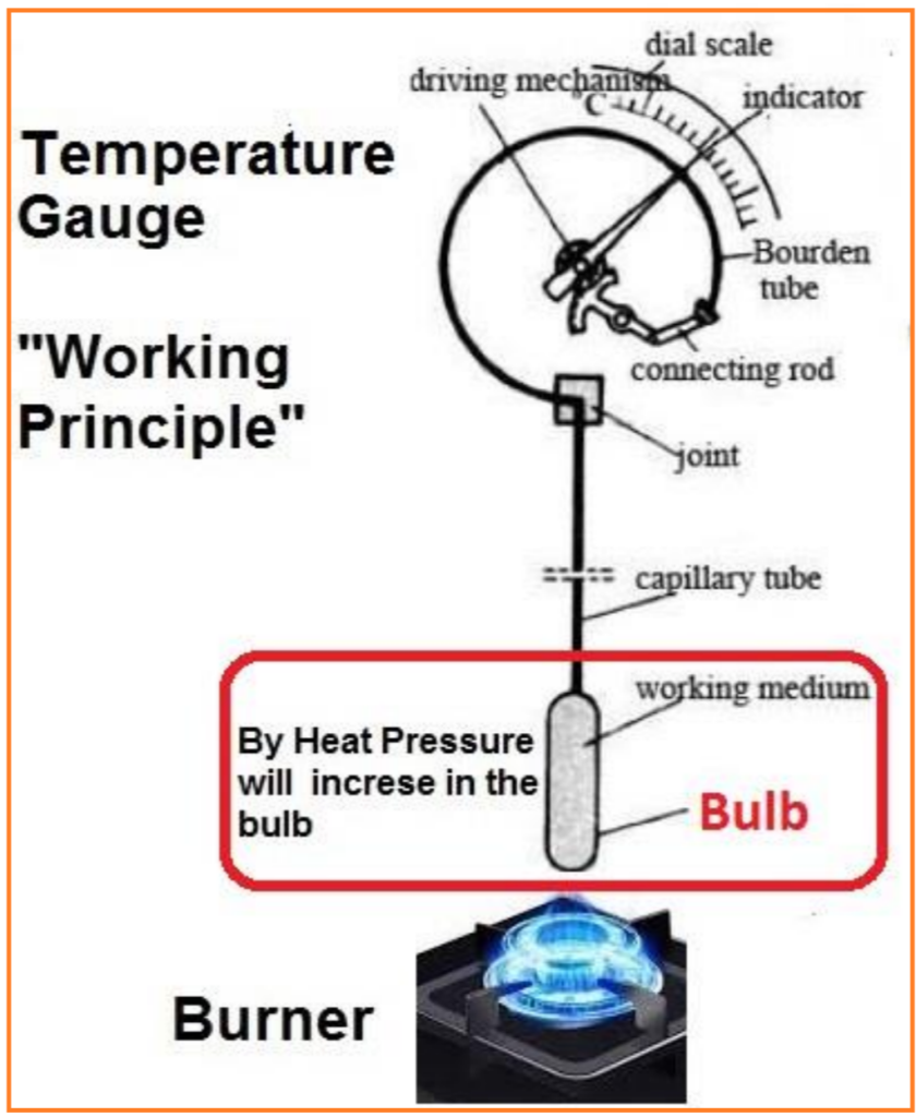
Temperature Gauge
It is just like a pressure gauge having Bulb welded with input port.
Filed with mercury or gas. Heat expands the Mercury or Gas in the “C” bourdon.
This expansion of bourdon is transferred to movement assembly.
Which moves the pointer on the temperature graduated scale?
By heating the bulb, we can read the temperature of any process.
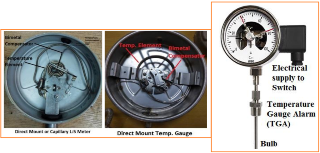
Ambient Temperature Compensation in a Temperature Gauge
We have 2 types of temperature gauges used in industrial instrumentation.
1- Direct mount temperature gauge, which is directly installing in the process pipe under sun shine.
2- Remotely mount temperature gauge, which has capillary length from 3 meters to 20 meters or more. In this system temperature gauge is always away from the Temperature sensor (Bulb).
Capillary Tube:
Capillary tube is thin SS tube (Filled with Liquid or Gas. It is covered by metallic and plastics sheath and laid down in the cable trey under sun. Due to the atmospheric heat effects gas or liquid filled in the SS capillary is affected and ambient temperature is adding in the process variable reading.
Temperature Compensation:
A compensation system is installed in the temperature gauge to take actual temperature of process variable. This system removes the ambient temperature effects from the actual reading of process. It works opposite of main sensor in the gauge. That is the reason, we need temperature compensation system in the all temperature gauges.
There are 2 types of temperature compensation in a temperature gauge.
1- Bimetal compensation
2- (2) Lead / Capillary Type Compensation.
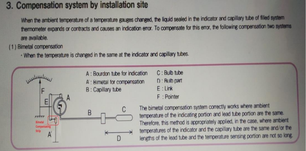
(1) Bimetal compensation.
This type of compensation is always used in direct mount temperature gauges or very short capillary type temperature gauges, It is 2 different types of metals (Bimetal plates) fixed before movement assembly which is always opposing the main capillary movement to reduce ambient temperature and true movement will be transfer to the movement assembly to reach the pointer, as shown in these pics.
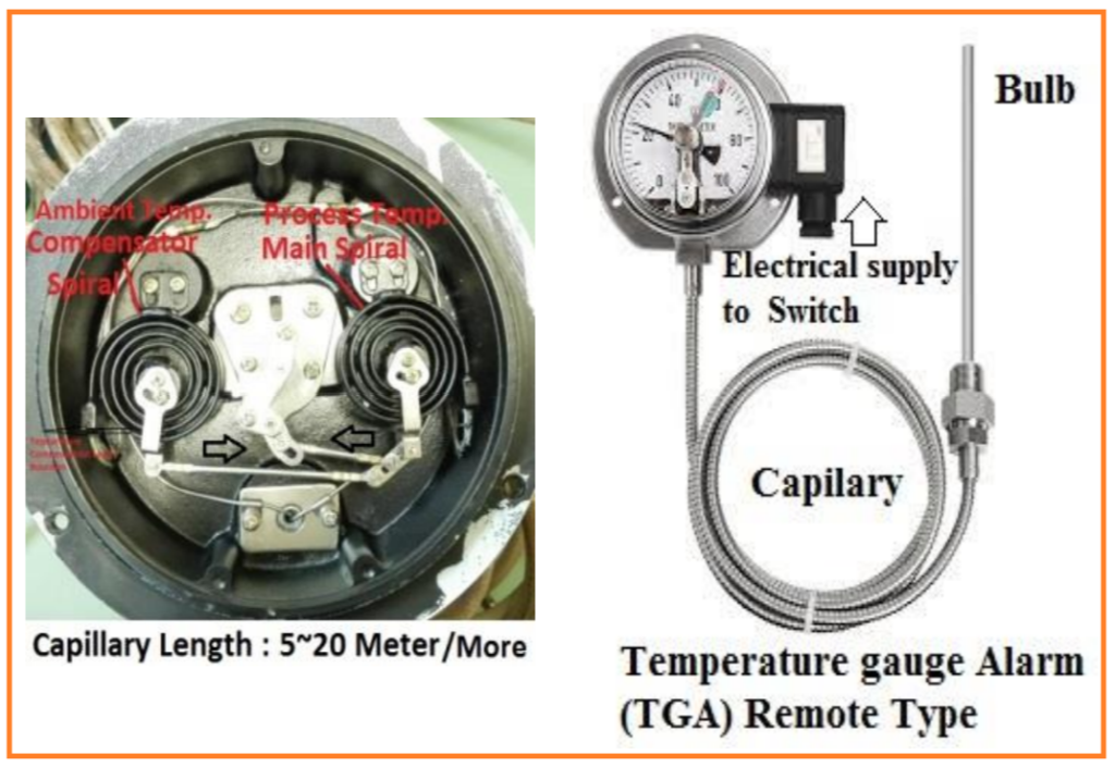
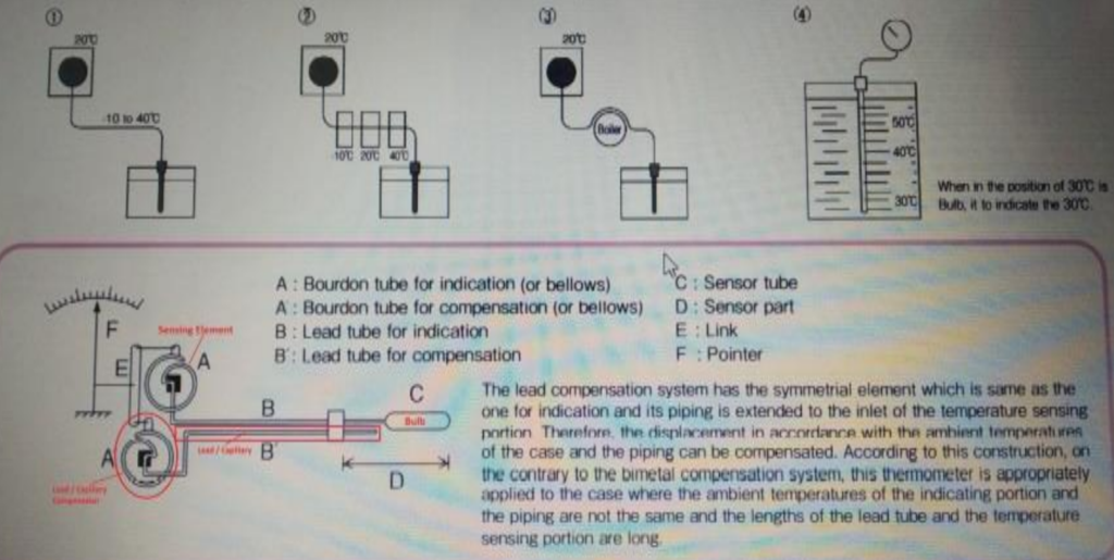
(2) Lead Type Compensation:
This type of compensation is always used in remote mount temperature gauges having long capillary. (From 3 Meter to 20 Meter or more).
In this compensation a 2nd Lead / Capillary is used along with main capillary but don’t have sensing bulb and end point is always finished before bulb of main capillary. So ambient temperature effects on both capillaries in same ways and in the gauge a second pressure sensor is installed which is attached with 2nd Lead / Capillary.
This temperature sensor is always fixed to oppose of the movement of main capillary sensor. The difference in between 2 pressure sensors will be transfer to the movement assembly to move the pointer and will show the actual temperature of process variable on the temperature scale. As shown in the fowling pics.
Temperature Switch
In any temperature gauge, if a Micro Switch is installed and can be adjusted the Set Point on a certain temperature then gives output ON-OFF contacts. It is called a temperature switch. As shown below.
Draw-back of a Temperature Gauge:
Temperature gauge is always installed it the field.
Temperature gauge can’t send temperature in control room to record and control.
Whenever we need to know the temperature of any process, an operator should go in the field to take reading.
Temperature gauge can’t control the temperature at required set point.
Note: But we need to know all process temperatures in the control room for
recording and controlling purposes.
So we need some other types of sensors which detect temperatures and transfer these temperatures values in the control room for recording and controlling.
We have 2 types of sensors.
(a) Thermocouple (T/C)
(b) Resistance Temperature Detectors (RTD).
Thermocouple (T/C)
Thermocouple is a device which is made by two different metals and defused at one end. (Never welded with any other material)
T/C always used with the measuring bridge which amplify mV signal in to volt (V) or current (I).
By heating of the defused end (mV) produces. This is called Hot Junction.
Hot junction is using as a sensor to measure the heat in process.
Ice pot can be used as a Cold Junction to test the loop of thermocouple.

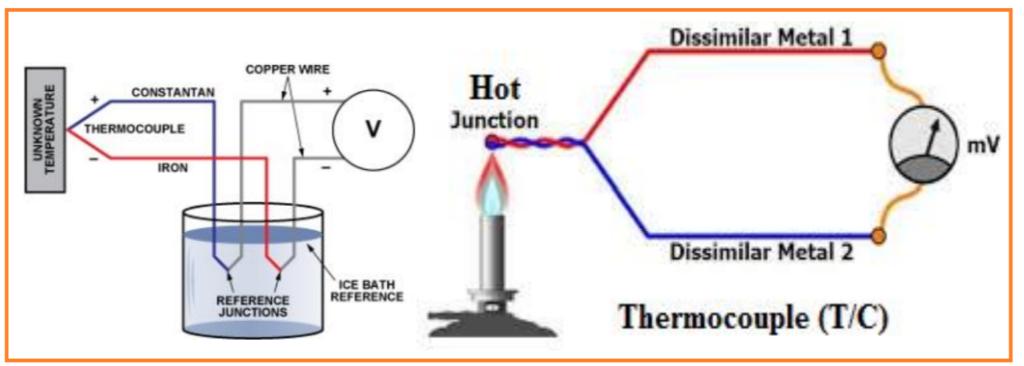
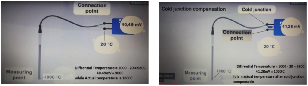
Ambient Temperature Compensation in Thermocouple
Thermocouple doesn’t measure absolute temperature. (“0” Kelvin)
Thermocouples measure the differential temperature between the measuring point (Hot Junction) and the connection point of Transmitter / Converter. That’s why thermocouples also need a cold junction compensation, which ensures that the ambient temperature at the connection terminals of the cold junction does not change the measuring result & Showing accurate reading.
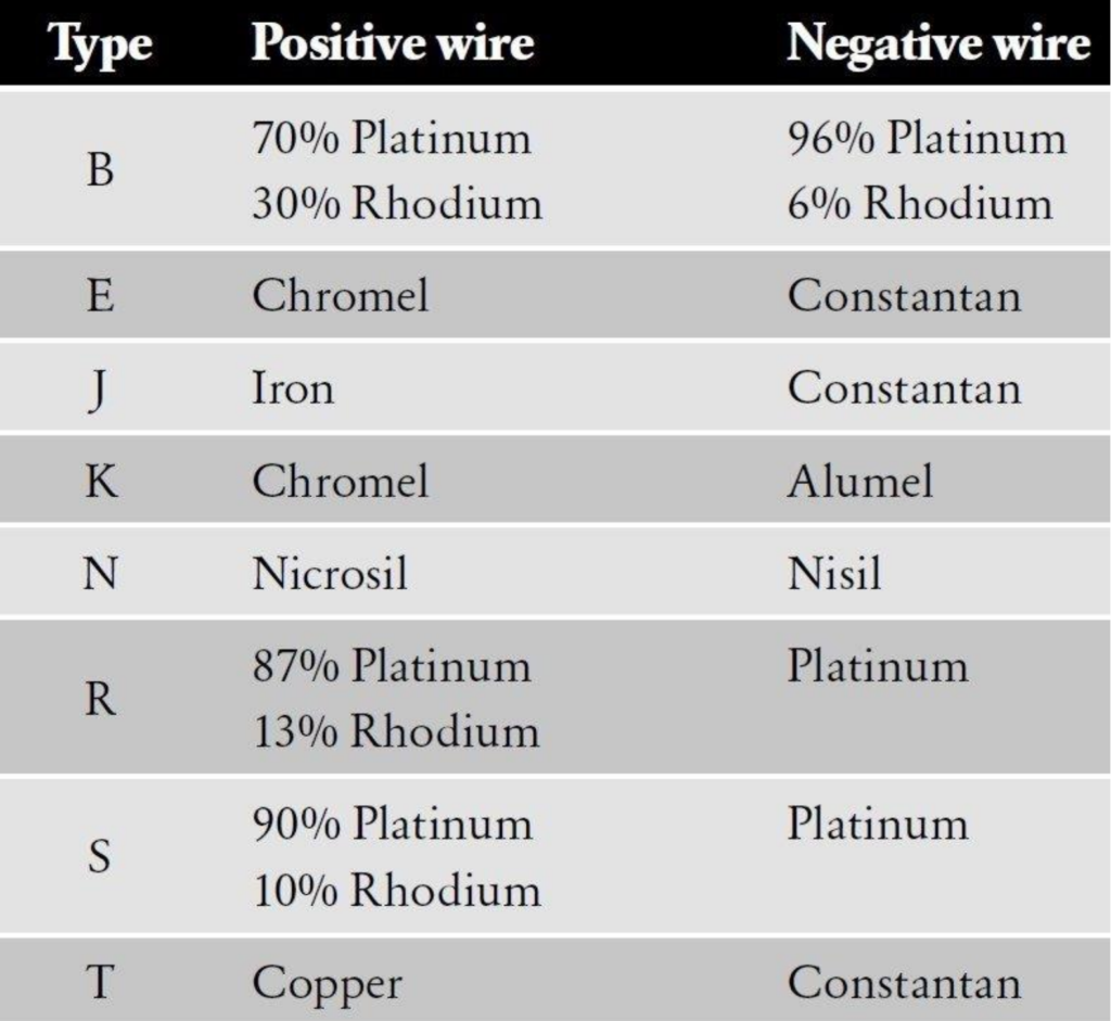
There are many types of thermocouples (T/C) available with different ranges of
temperatures.
TYPES: K, J, T, E, N, S, R & B, Mostly 3 types are used: (T) type, (J) type and (K)
type. Each T/C has different ranges of temperatures with color codes.

Material used in each type of Thermocouple:
Resistance Temperature Detector (RTD)
RTD is a device which is made by a special resistance (Pt100 having resistance 100 ohms at “0” degree C), whose resistance value changes with the heat. This is good for low temperature. 0 to 260C)
By heating the resistance of RTD, there is change in resistance which is always
proportional to the temperature.
RTDs are always used with the measuring bridge (RTD to V/I Converter) which
converts resistance in to Volt or Current.
This Signal transmits to indicator or recorder to show accurate temperature.
Note: There are 2 wires, 3 wires and 4 wires RTD.
Most commonly used RTD is 3 wires.

RTD, Red wire showing Positive and other two white / blue wires shorted with each other in the sensor used as Negative as shown above picture.
Most commonly use of RTD is to measure winding temperature of motors, transformers and generators where thermocouple could not use because of high voltages.
Level
1- A measurement in between two altitude points is called level.
2- Level means any liquid filled in a tank and travelling vertically from one altitude
point to other altitude point is called level.
3- Vertical Height from the reference point is called Level.
4- Level of any liquid is producing head pressure at bottom of the tank. Head pressure at bottom of tank will increase if level in the tank will increase.
5- At zero level head pressure will also be zero. Means there is no water in the tank.

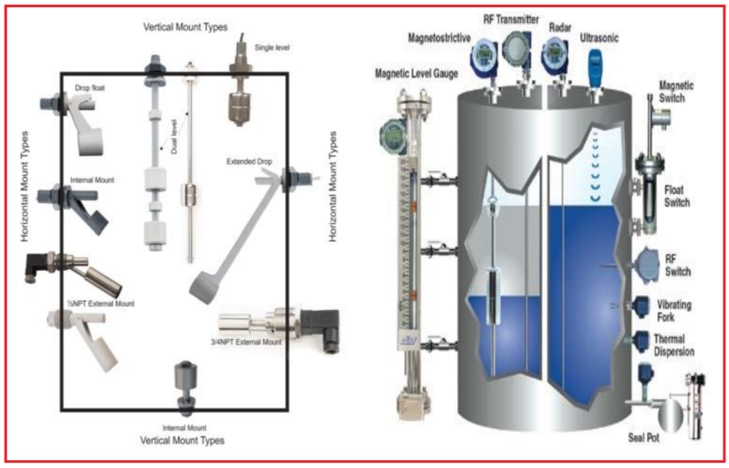
Sensors of level measurement
There are many level sensors available in the market. Basic few level sensors are as follows.
1- Level glass with measuring scale or ruler as shown in above picture.
2- Pressure & Differential Pressure (DP Cell) measuring water head pressure in the bottom of the tank.
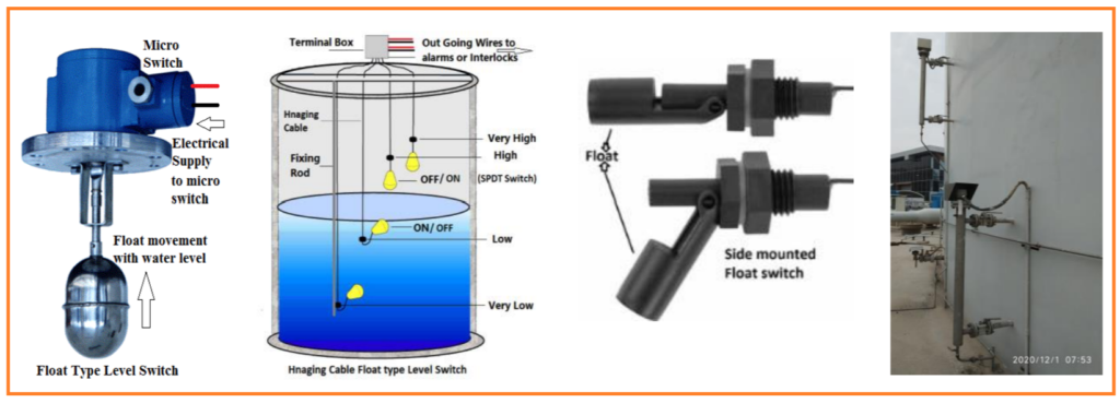
3- Floats in different designs and sizes having vacuum in it. Floating along with water level.
4- Displacer having specific weight according to the medium. It displaces the liquid and liquid will create bouncy power to lift this weight but it will loss his weight according to the displaced liquid.
5- Electrodes type conductivity based contact types level sensors.
6- Ultrasonic Wave, Magnetic Float, Flat Board and many more sensors used to measure level.
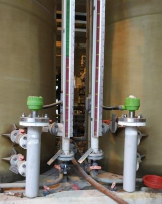
Local Level Glass Gauge: Directly attached with tank. Made by glass and
graduated in Meter WC, mm WC or Inches of WC or feet WC. As shown in above &
below Pictures.
Different Types of Float Sensors: There are many types of floats and Displacer used for level measuring system.
Float moves along with water level.
Pressure and Differential Pressure sensors can be used as level sensors.
Magnetic Float Type Level Gauge:
Magnetic float is floating in chamber behind the level indicator. It moves up & down along with liquid level. Moving plates are fixed in a trail vertically and panted one side Red and other side Green or White. When float rises with liquid level, due to the magnetic flux, plates change their position from Green to Red and when level fall down plates changes their position from Red to Green.
Red means the Level in the tank. Green means the empty portion of a Tank.
Flat Board Float Type Level Gauge:
This type of float is used in very large sizes of tanks. Floats moves along with liquid in the tank and hold by 2 guide wires. This float hangs with steel strip and it moves on the 2 rollers. Steel strip roles in a Level Gauge which has 2 needles. Big needle moves on Meter scale and Small needle move on CM scale.
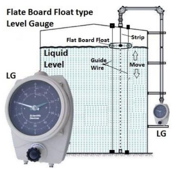
Read More Explanation about Flat Board Float Type Level Gauge in details.
Level Switches:
When Micro switches used with, floats and Displacers in level gauges are called level switch, level switches giving alarm to control rooms and also used for interlocks.
There are many types of Floats and displacers available in the market.
Read More Explanation about Level Switches in details.
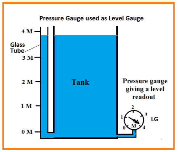
How a Pressure Gauge & Pressure Transmitter is used in Level Measurement?
It will only measure liquid level head pressure from one altitude point to 2nd altitude point,
Pressure Gauge scale will be graduated in Meters or mm H2O as shown in this diagram.
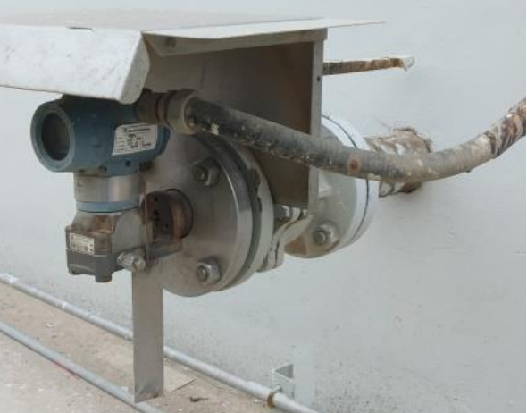
Pressure Transmitter will also measure liquid level head pressure from one altitude point to 2nd altitude point and convert head pressure in to electrical signal 4~20mADC to transfer from field to control room.
Pressure & Differential Pressure sensors are used as level sensors.
Displacer:
Mostly used in Level switches & Level Transmitters.
It has specific weight. Displacer loses his weight according the principle of Archimedes.
If water increases, water bouncy power will try to move the displacer upward. It moves few mm upward because of weight. This movement is transferred through torque tube to transmitter to convert 4~20mADC and transmitter will transmit this signal to control room to show level on indicator or recorder and control.

Read More Explanation about Displacer in details.
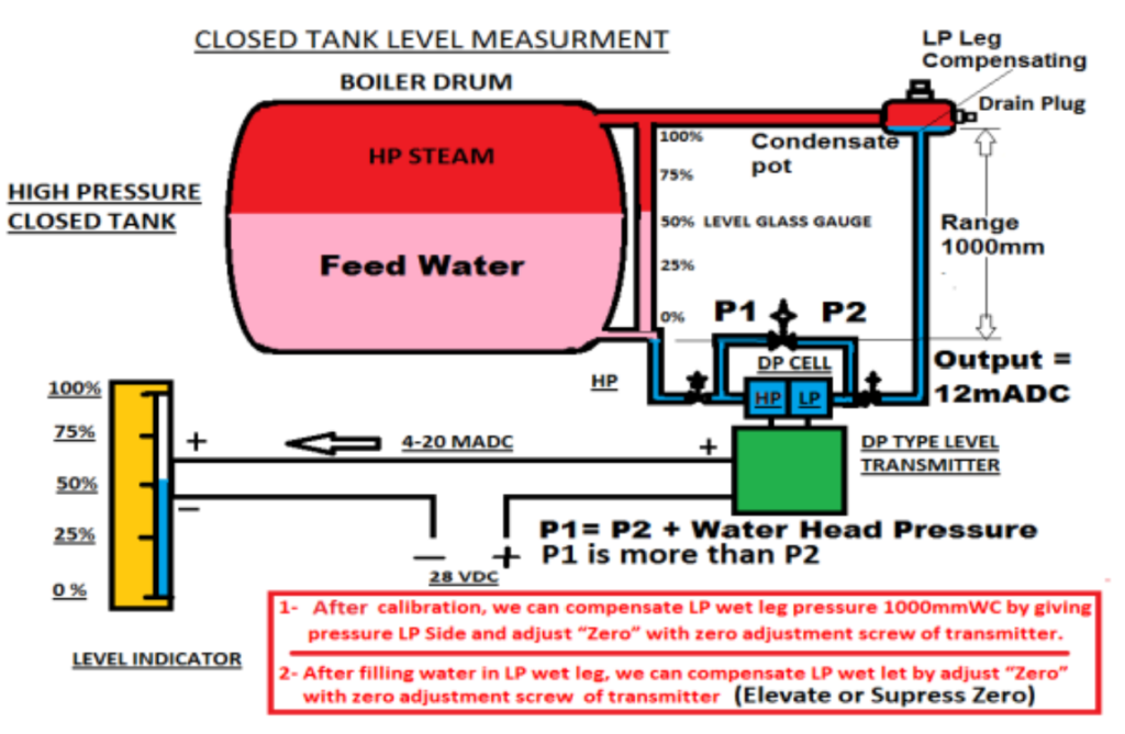
DP Cell: (Closed Tank Level)
In closed tank High side (HP) attached bottom of the tank and Low side (LP) attached at the top of the tank. It will measure the differential pressure which is
graduated on the indicator as level of tank.
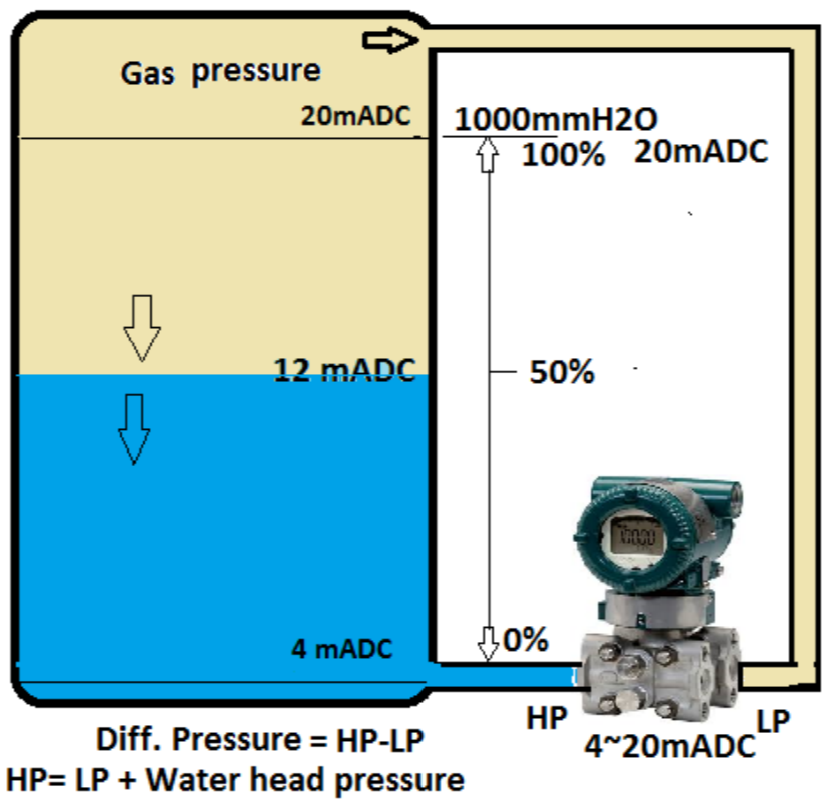
Like: Drum Level in Boiler
Level means Diff. Pressure = HP – LP. If HP pressure is P1 & LP pressure is P2 The Differential Pressure = P1 – P2 Then P1= P2 + Water Level Head Pressure in tank.
Read More Explanation about DP (Differential Pressure) Cell in Closed tank Level in details.